Ben I have built your amp and it is working as intended. I have the front end preamp kit and I
wonder if you could help me with the connections.I will be using a 48v single supply.Single ended input
and single ended output.Does the ground of the input go to -N and does the ground of the output go
to V-. Thanks for any help you can give.
wonder if you could help me with the connections.I will be using a 48v single supply.Single ended input
and single ended output.Does the ground of the input go to -N and does the ground of the output go
to V-. Thanks for any help you can give.
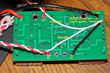
That is great news that the amp is now working. Now we need pictures.
For the DIY FE 2022 with a single ended V+ power supply, do not install R10 and replace it with a wire. The V- input on the board becomes Ground.
For single ended input, connect IN- on the board to Ground.
Power supply ground, input ground, and output ground all connect to Ground
For the DIY FE 2022 with a single ended V+ power supply, do not install R10 and replace it with a wire. The V- input on the board becomes Ground.
For single ended input, connect IN- on the board to Ground.
Power supply ground, input ground, and output ground all connect to Ground
Ben
I've made the changes you suggest to the PCB and installed new parts for the independent bias supply. It appears to be working. With a 60V DC input, the maximum bias voltage at the SIT gate (SIT in circuit, no V- connected) is around -46.8V. But it takes quite a while to build up and stabilise and respond to adjustments of RV1. I'm using a 1000uF 100V Nichicon KW for C1A mounted on the board temporarily, no C1. All other components are as per schematic.
Any ideas what might be causing the delay in bias voltage build up and stabilisation when adjusted?
Thanks.
More than 10 minutes to stabilise at maximum bias voltage from initial switch on. If the trimmer is then adjusted, several minutes to stabilise at the voltage.
Power source is 36V Meanwell SMPS feeding into a DC-DC boost converter to provide 60V. The output from this measures a rock solid 60.0V regardless of bias supply voltage. It has about 1mF of filtering on its output. The SMPS and booster were on hand so I thought they may be worth a go. Perhaps not? I don't have a 48V transformer on hand. Would one with dual 30V secondaries in series (60V) produce too much raw DC for the regulator?
Power source is 36V Meanwell SMPS feeding into a DC-DC boost converter to provide 60V. The output from this measures a rock solid 60.0V regardless of bias supply voltage. It has about 1mF of filtering on its output. The SMPS and booster were on hand so I thought they may be worth a go. Perhaps not? I don't have a 48V transformer on hand. Would one with dual 30V secondaries in series (60V) produce too much raw DC for the regulator?
Yes, it could be the complicated power supply
The simplest and best solution is a transformer and bridge rectifier. The current draw per channel is only about 20mA so a 5VA transformer will do.
With your 60VAC transformer, you could put a 1.3k resistor in series after the rectifier. At least 1W resistor, more for cooler operation. You can measure the voltage at the capacitor when turned on. Make sure that it is at least 60VDC. There may be a much higher voltage at start-up, perhaps even higher than the 80V rating of the capacitor. So this would be only a temporary check to see how fast the bias voltage comes up.

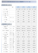
I have this information for Tokin - see attachments.
The pdf article does not include the THF-51S but it does include other Tokins. It specifies the maximum Vgs as 70V (not -70V) but perhaps they meant -70V.
The second attachment is mostly in Japanese but there is a row which shows 70V for the Tokins except 50V for the THF-51S. Perhaps this is also maximum Vgs.
If the maximum Vgs for the THF-51S is indeed -50V, then a 50V zener would work.
Attachments
What is happening is that with with V- present there is voltage on both sides of the zener so that the net voltage across the zener is less than the zener voltage, and all is good. When the bias voltage is higher than the zener voltage and there is no V- present so that there is no voltage on the other side of the zener, the zener will conduct. What is on the other side of the zener is the big 10mF output coupling capacitor, which then takes current from the bias supply.
A zener with a voltage higher than the bias supply voltage will prevent the bias supply to provide current to the output capacitor.
You can test this by removing the zener and also have the Tokin disconnected to be on the safe side, and fire up the bias supply without V-.
A zener with a voltage higher than the bias supply voltage will prevent the bias supply to provide current to the output capacitor.
You can test this by removing the zener and also have the Tokin disconnected to be on the safe side, and fire up the bias supply without V-.
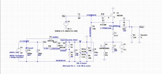
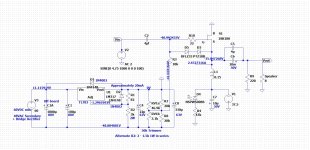
Since I have a LTSpice model of the circuit, I did simulations with the 18V zener and 0V-, 51V zener and 0V-, and 51V zener and -37.5 V-. The length of simulation was 100mS. The 18V zener circuit showed the bias at -19V and the 51V zener circuits showed the bias at -40V. So the 18V zener is the issue when an independent bias supply is used in this circuit.
Attachments
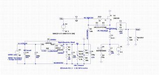
Using two 20V zeners and the existing 18V one, bias started instantly (no V-). I then connected V- (37.5V) and powered up at maximum bias. All OK, 0V across choke, Vds = 37.5. Trimmer was then slowly turned clockwise in stages to get 2.5V across the choke (Iq = 2.5A). At this point, Vds = 34.91V, Vg = -38.4. I powered down and restarted a few minutes later at the same Iq, no problems. This was repeated some time later with the same result. I connected the amp input to the output of a DAC/preamp, hooked up some headphones and listened to a bit of music. Only one channel at present but it seems to have a similar sound to the V+ version, which isn't surprising. Also, its dead quiet. In due course I'll build both channels into the existing V+ version chassis.
Ben, my knowledge of solving problems with even simple designs such as this is clearly very limited. I would not have sorted this without the knowledge, time and patience you provided. This is greatly appreciated. It might also be useful for others who may be considering using SMPS's with this or similar designs.
Ben, my knowledge of solving problems with even simple designs such as this is clearly very limited. I would not have sorted this without the knowledge, time and patience you provided. This is greatly appreciated. It might also be useful for others who may be considering using SMPS's with this or similar designs.
- Home
- Amplifiers
- Pass Labs
- 25W Single Ended Hammond 193V Choke Loaded 2SK180 L'Amp