Hi Adrian,
The CL-60 is good.
Your diagram of the transformer 30VAC secondary wiring is incorrect. The two blue secondary wires should connect to one AC lead of the bridge rectifier and two green secondary wires should connect to the other AC lead of the bridge rectifier. For the 15VAC secondaries, use only on secondary winding. Connect one brown secondary wire to one AC lead of the bridge rectifier and the other brown secondary to the other AC lead of the bridge rectifier. The other 15VAC winding is not used.
The transformer purple wire for the shielding connects to chassis ground.
For the snubbers, both have the same capacitor values. Only the resistor value is different. As noted in my previous post, use 33R for the paralleled 30VAC and 29R for the 15VAC.
The DIY FE 2022 has a fixed gain of 10 but if you wish to use it as a preamp, you can put a volume pot at the input. A 50k volume pot should do.
Attachments
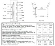
As for power up and testing, the power supply should be tested on its own first before connecting it to the amplifier board. Even better would be to test the power supply in stages. First stage test after snubber and rectifiers in place. Check for DC voltage output at the rectifiers. Second stage test after the CLC power supply filter in place. Check for DC voltage output at the PS output. In all tests, start with a Dim Bulb Tester (DBT) in place. The bulb should dim after an initial brightness. If it continues to glow bright, there is an abnormal current draw (short) somewhere. If it passes the test, then it can be powered up with the DBT removed. With no load attached to the power supply the voltage will be high, perhaps around 40V.
But before powering up, double check the wiring against the schematic/diagram. Be sure everything is wired and connected properly.
When connecting the amplifier board and components, again double check wiring and connections. The trimmer pot for bias should be at full counterclockwise. Connect a voltmeter to two Test Points on the amplifier board that are connected to the 193V choke (T.P. V- Choke 1 and T.P. SIT S Choke 2). The DC resistance of the 193V is 1 Ohm so by Ohm's Law, the measured voltage drop across the choke is also the current (1V = 1A). If you have a second meter connect it to T.P. GND and T.P. V- Choke1 to monitor the power supply voltage.
First amplifier board power-up is with DBT in place. There may be an initial surge of current but that should drop to zero. If all is well, start turning the bias trimmer pot clockwise and watch the voltmeter. At some point the voltage across the choke should start to rise, and stabilize when you stop adjusting the trimmer. That is a good sign that all is well. Turn the trimmer pot counterclockwise to set the current back to zero. Power down and remove the DBT. Power up with full AC keeping an eye on the meters. It may initially show a small current surge but should settle at 0A. Turn the trimmer pot clockwise until the current is approximately 1A. Put the amplifier chassis cover in place and let the amplifier heat up and stabilize. As the SIT temperature increases, the current may also increase. Then continue by increasing the current in approximately 0.5A steps. The goal is to stop at a final stable current of 2.5A.
Note that at the Test Point locations on the amplifier boards I soldered a small wire loop to to the T.P. pads so that meter clip leads may be easily attached for hands free measurements.
Attachments
Last edited:
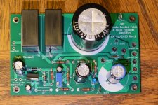
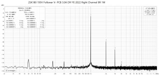
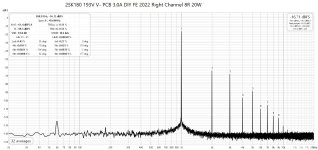
Since Adrian is building this choke loaded follower with a THF-51S in place of the 2SK180, I decided to see what this amp can do with higher Iq. I also realized that since I changed the amp from common source to common drain, I did not try to see how much power it can actually put out. So with Iq set at 2.5A, I pushed the power as far as my Victor oscillator and 62.5V PS DIY FE 2022 could go. At maximum oscillator and DIY FE voltage output, I measured 33.3W at 8 Ohm and 4.52% THD. For distortion figures at lower power output, see https://www.diyaudio.com/community/...-choke-loaded-2sk180-lamp.366312/post-7420685.
Attachments
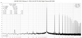
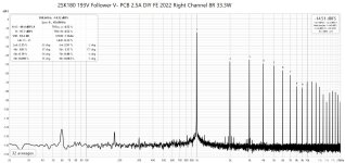
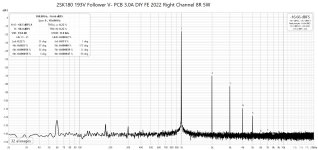
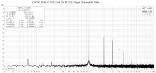
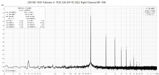
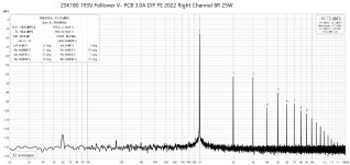
So then I upped the Iq to 3.0A. That put the dissipation at 104W. The 2SK180 is a 300W device so 104W was 35% of that. I think that is doable as long as the heatsink is big enough to keep the SIT at a comfortable temperature. The THF-51S is a 400W device so there is a much larger comfort level.
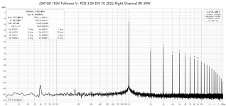
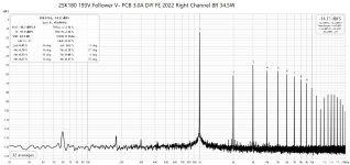
The higher Iq resulted in slightly higher distortion at low output levels but much improved distortion performance at higher power output.
35W at 8 Ohm looked good with an Iq of 3.0A. So I would call this choke loaded Tokin follower a 35W amp.
The higher Iq resulted in slightly higher distortion at low output levels but much improved distortion performance at higher power output.
35W at 8 Ohm looked good with an Iq of 3.0A. So I would call this choke loaded Tokin follower a 35W amp.
Attachments
-
 2SK180 193V Follower V- Right Channel 3.0A DIY FE 2022 8R 1W.jpg240.4 KB · Views: 12
 -
 2SK180 193V Follower V- Right Channel 3.0A DIY FE 2022 8R 5W.jpg240.1 KB · Views: 9
 -
 2SK180 193V Follower V- Right Channel 3.0A DIY FE 2022 8R 10W.jpg238.9 KB · Views: 9
 -
 2SK180 193V Follower V- Right Channel 3.0A DIY FE 2022 8R 15W.jpg240.7 KB · Views: 10
 -
 2SK180 193V Follower V- Right Channel 3.0A DIY FE 2022 8R 20W.jpg238.8 KB · Views: 9
 -
 2SK180 193V Follower V- Right Channel 3.0A DIY FE 2022 8R 25W.jpg241.3 KB · Views: 10
 -
 2SK180 193V Follower V- Right Channel 3.0A DIY FE 2022 8R 30W.jpg243.2 KB · Views: 10
 -
 2SK180 193V Follower V- Right Channel 3.0A DIY FE 2022 8R 34.5W.jpg243.9 KB · Views: 11
don't fret about difference between 300W and 400W
for our purposes, both are waaaaay high enough, so you can throw on tough buggers whatever you want, as long you didn't put cardboard instead of decent thermal isolator
I can bet that any of Big Tokins is going to outlive anything in surrounding, including fuses, in case of some major ookup
for our purposes, both are waaaaay high enough, so you can throw on tough buggers whatever you want, as long you didn't put cardboard instead of decent thermal isolator
I can bet that any of Big Tokins is going to outlive anything in surrounding, including fuses, in case of some major ookup
Hi ZM, The highest power dissipation that the 2SK180 sees in this amp is at startup. Since the bias voltage is not from a single supply but from a lower voltage supply stacked on top of the main power supply, the bias voltage does not reach full voltage before the SIT drain/source voltage does. With the amp set up for 3.0A when hot, at startup one of the channels showed a momentary current of approximately 11A. Momentary Vds would be around 26.5V for 292W of dissipation at ambient temperature for a moment. So close to maximum of 300W but not close to the maximum of 20A.
Nothing to worry about.")
The other channel's maximum momentary current at startup was about 10A. So no worries there either. They will probably outlive me.
Nothing to worry about.
The other channel's maximum momentary current at startup was about 10A. So no worries there either. They will probably outlive me.
My THF51s have shown great resistance to my attempts to harm them unconsciously.
Mine will outlive me. I cannot imagine ever replacing them.
My gratitude to those who have given us these designs and guidance: The Beloved Great Man, Zen Mod, Ben Mah and Rahul/ra7 in learning how to use these.
Mine will outlive me. I cannot imagine ever replacing them.
My gratitude to those who have given us these designs and guidance: The Beloved Great Man, Zen Mod, Ben Mah and Rahul/ra7 in learning how to use these.
- Home
- Amplifiers
- Pass Labs
- 25W Single Ended Hammond 193V Choke Loaded 2SK180 L'Amp