Maybe you should read again:Not really my readng
Output-to-output skew: 500ps vs 50ps
Additive jitter: 150ps vs. 20 ps
Max input frequency: 150MHz vs. 250MHz.
Phase noise: -85dBc@10Hz vs. 85dBc@1Hz
Much simpler and takes up less space. You need to sharpen your math skills as well: LMK1C1104DQFR = 1.4€, 3x NC7WZU04 = 0.9€.Yes, but it's likely no better than a pair of suitable CMOS inverters. So I have doubts that there is any reason to chose a single source, 8 times more expensive device.
Output-to-output skew: 500ps vs 50ps
Irrelevant in our case.
Additive jitter: 150ps vs. 20 ps
Peak? RMS? Bandwidth?
I'd rather see the phase noise plots.
But, my preferred inverters are no specified for this. What I do know is that have been used as clock buffers for DAC MCK in products that show much, much, much less than 150ps Jitter. So I can neither qualify or place into context your numbers.
Max input frequency: 150MHz vs. 250MHz.
Again, not particularly relevant. Even comparing propagation delay is not simple, as the capacitive load in test circuit is very different.
Phase noise: -85dBc@10Hz vs. 85dBc@1Hz
Where do you find a phase noise plot for NC7WZU04?
Much simpler and takes up less space. You need to sharpen your math skills as well: LMK1C1104DQFR = 1.4€, 3x NC7WZU04 = 0.9€.
Funnily enough, at mouser both have no stock. But NC7WZU04 has multiple alternative parts with 1,000's ready to ship.
My price comparison was actually LMK1C1106PWR (> 3 USD) vs 74LVCU04PW (0.35cent each).
Actually, it illustrates my point to avoid non- generic parts as much as possible. If it has not at least 3 sources and additionally a good supply of Chinese generica it is best avoided.
Thor
Try reading again what 2 buffers I compared:
https://www.diyaudio.com/community/threads/return-to-zero-shift-register-firdac.379406/post-7663201
https://www.diyaudio.com/community/threads/return-to-zero-shift-register-firdac.379406/post-7663201
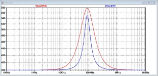
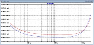
Marcel, I simmed your revised proposal.
FR between old and new is identical.
Impedance as seen from the equivalent Firdac voltage source is slightly improved, blue for new and red for old.
And even the noise generated for the revised version has been improved, also blue new and red for old.
So it seems to be an improvement.
Hans
FR between old and new is identical.
Impedance as seen from the equivalent Firdac voltage source is slightly improved, blue for new and red for old.
And even the noise generated for the revised version has been improved, also blue new and red for old.
So it seems to be an improvement.
Hans
Attachments

Try reading again what 2 buffers I compared:
https://www.diyaudio.com/community/threads/return-to-zero-shift-register-firdac.379406/post-7663201
Seems we have an intermodulation problem between two entirely separate conversations. I have said what needed saying anyway.
Thor
Reading carefully the additive jitter is 150fs and 20fs, not 150ps and 20ps. 😉Maybe you should read again:
Output-to-output skew: 500ps vs 50ps
Additive jitter: 150ps vs. 20 ps
Max input frequency: 150MHz vs. 250MHz.
Phase noise: -85dBc@10Hz vs. 85dBc@1Hz
Much simpler and takes up less space. You need to sharpen your math skills as well: LMK1C1104DQFR = 1.4€, 3x NC7WZU04 = 0.9€.
Decided to do a future comparison between NB3L553 and LMK1C110x clock buffers. Did some tests with the former buffer today. One of the the requirements of my clock board is that it be able to drive various dac boards that a diy'er might be interested in using. It turns out that Andrea Mori likes parallel end termination (Thevenin topology, IIUC) for some of his boards, with his FIFO board being one example (which I use here).
Driving a 50R line with effectively 50R end termination can be a challenge for CMOS parts. In particular NB3L553 can do it, but it gets jittery sounding without some source series damping of the line. Guessing the jittery sound is from some kind of current limiting kicking in every clock cycle. Using 27R or 33R source series resistance makes the sound not jittery but pretty blurry instead (like too much phase noise). Going down to 15R series resistance just starts to get into jittery sounding territory. At 15R the jitter sound can start to sound more dynamic and crisply focused, but it seems to be an illusion of the jitter. Cymbals start sounding like noise bursts, drums all have the same body resonance, etc. However, there appears to be a Goldilocks point at about 20R where blurring is minimized, dynamics are still intact, and jittery sound is pretty much absent. Still not as detailed and refined as SOA clocks, yet very nice listening.
The good sounding clocking is simply from clean power, film bypass caps on everything, thoughtful layout, low phase noise frequency division, and buffering of the output. I have been hinting about this stuff for a long time, at least it seems like it. But guess it will take a shared project to show an example. Then it will be on to the subject of reclocking and galvanic isolation next. With those two things done, hopefully that part of diy dac design will start to gain some increased interest/momentum.
With further work on Marcel's dac too and the use of PCM2DSD (previous firmware version) and or HQ Player, maybe we will be at the point of high end DACs for diy'ers that are better than anything Topping or other dac chip based designs can typically do.
Last edited:
It turns out that Andrea Mori likes parallel end termination (Thevenin topology, IIUC) for some of his boards, with his FIFO board being one example (which I use here).
Hmmm, this has both advantages and disadvantages. Signal swing is reduced from 3.3V PP to appx. 2.5V and there is a lot clock derived current feeding into the PSU.
Driving a 50R line with effectively 50R end termination can be a challenge for CMOS parts.
For LVC logic you get around 30 Ohm for the saturated P-Channel part and 20 Ohm for the saturated N-Channel part. In between, around the midpoint where the actual triggering happens in the downstream part both parts conduct and the impedance is not very well defined.
It is possible to adjust the P-Channel geometry to make resistance equal, but now capacitances are very different. Marcel is the expert on that.
Any complementary structure will struggle on some parameter as the P & N - Channel parts are just not really that complementary.
In particular NB3L553 can do it, but it gets jittery sounding without some source series damping of the line.
You do need to terminate the line at either beginning only or at both ends. The NB3L553 is rated as 20 Ohm nominal, so it needs around 27 Ohm to match a 50 Ohm line. BUT the "nominal" Impedance is just that, nominal. I normally tune the series resistor looking at the waveform at the receiving end and before the driver and aim for a fast edge with no overshoot. 1:100 Probes or active probes.
Guessing the jittery sound is from some kind of current limiting kicking in every clock cycle.
Overshoot at the source end, due to impedance mismatch?
Using 27R or 33R source series resistance makes the sound not jittery but pretty blurry instead (like too much phase noise).
Slow edge rate creating more phase noise?
However, there appears to be a Goldilocks point at about 20R where blurring is minimized,
I'd like to see some 'scope screens.
If abandon "canned" single vendor parts, a common solution to driving clocks with terminated lines is a 74XXU04 with 5 gates paralleled. The following assumes a coax cable, high quality connectors (e.g. SMA) and AC coupling.
If we have a 3.3V clock and use 74LVCU04 we get 4 Ohm low and 6 Ohm high, so 45.5 Ohm (2 X 91 R in parallel) series termination gets us right onto 50 Ohm. The output coupling Capacitor should be relatively large.
At the receiving end we use this schematic:
Unbuffered Inverter. A 74LVCU04 or multiple NC7WZU04 could be used to add clock fanout.
A 100 BaseT or 1000 BaseT isolation transformer could be added for galvanic isolation.
Then it will be on to the subject of reclocking and galvanic isolation next.
For galvanic Isolation, if we have an RTZ signal, we could just use an isolation transformer (100 Base T ethernet?) with a suitable driver circuit for isolation. Here a Bourns SM51589PEL:
The Transformer could be inserted in Marcel's DAC after the OR Gates that create the RTZ signal (U9/U25) which could possibly directly drive the transformer directly or via a small buildout resistor.
The receiving end might be good enough using the circuit below.
The termination resistor for the transformer should be selected based on monitored waveform, 330 Ohm might be a starting point. As there are RC delay circuits in the original, they should be retained and retuned.
Alternatively adding LVDS Driver and Receiver IC's before and after the transformer is a more proper solution. Quad Driver and Receiver IC's with identical pinout are available from a range of sources, eg. DS90LV031/DS90LV032 and the wide range of parallel parts.
With MCK directly feeding the Reclocker Flip-Flop's and the Shift register chain we send an isolated MCK downstream using another transformer and drive the .
Thor
As has been shown previous FW of PCM2DSD does not work well with Marcel's RTZ dac. Since you still prefer that your comments about jittery or blurry sound have little credibility.With further work on Marcel's dac too and the use of PCM2DSD (previous firmware version) and or HQ Player, maybe we will be at the point of high end DACs for diy'ers that are better than anything Topping or other dac chip based designs can typically do.
@ThorstenL
Interestingly, the datasheet of LMK1C110x says it has 50R output Z, and a example is given of using it to drive an line with parallel end termination. Could be its worth trying first before getting into trying to analyze what is going on exactly. Thanks to bohrok2610 for suggesting it.

Also, some other things known about Andrea's dacs is that they are typically driven from sine wave oscillators. The FIFO board includes a squaring circuit on the input. Also, only upgoing clock edges are used so that square wave symmetry should not be an issue. So far, experiments in Italy and my own experiments have shown no limit to the audibility of low close-in phase noise has yet been found. Whenever lower phase noise clocks are used, there is always some audible difference. IOW, there always appears to be some audible degradation of digital audio when any close-in phase noise is added to whatever is imbedded in a recording when it is made.
Anyway, if I try LMK1C110x and I can get a little better SQ then great. However I won't be surprised if the phase noise of Accusilicon clocks ends up sounding a little worse than clocks with lower close-in phase noise. IME I have never heard a commercial dac that didn't have some audible jitter effects to the sound. What tends to tighten up the sound and give an illusion of focused sound typically sounds like a particular type of jitter effect. Cymbals and drums that don't sound real are easy ways to know something is wrong.
Regarding a calculation of the output Z of NBL553 at 20R driving a 50R line, IIUC the model of the source in would be a switch followed by a 20R resistor (inside the buffer), driving what is initially a 50R resistance. So we have a voltage divider with 20R on top and 50R on the bottom that give the pulse voltage launched down the line. Its only when a reflection comes back that a steady state solution starts to emerge. If there is reflection, then it has to be one that does not throw off the next pulse from the internal switch somehow (as evaluated at the time it reaches the receiver). Reflected energy may have to be dissipated somehow, and some source end damping may be the most practical solution.
Regarding slowed risetime as a possible noise source, not so sure its should be a problem unless maybe current noise from the source damping resistor is adding amplitude noise (maybe current noise) that get converted into phase noise as the signal passes through the squaring circuit receiver threshold. After all, the slow-ish rise time of low phase noise sine wave oscillators does not seem to be much of a problem in terms of obscuring the audible benefits of low close-in phase noise. Lower phase close-in noise sources are always audibly more focused sounding and give truer reproduction of instrument tones and textures.
------------------------------------------------------------------------
Regarding other folks here who may have some concern that this topic has is not applicable to Marcel's dac, I could not disagree more. Marcel's dac has some problems to be resolved before it can compete with the best of Andrea's dacs. That's my opinion. Also, its always easier to make a dac better if an even better reference dad is available for comparison. What's hard is when there is no better dac around. Then its easy to believe whatever is wrong with the sound must have been baked into the recording when it was made.
Also, regarding different versions of PCM2DSD firmware, I am not convinced the latest version is "better" with Marcel's dac. More likely what is still wrong does not show up well on an FFT because its not PSS. That makes the latest firmware the victim of listening with eyes instead of with ears.
Interestingly, the datasheet of LMK1C110x says it has 50R output Z, and a example is given of using it to drive an line with parallel end termination. Could be its worth trying first before getting into trying to analyze what is going on exactly. Thanks to bohrok2610 for suggesting it.
Also, some other things known about Andrea's dacs is that they are typically driven from sine wave oscillators. The FIFO board includes a squaring circuit on the input. Also, only upgoing clock edges are used so that square wave symmetry should not be an issue. So far, experiments in Italy and my own experiments have shown no limit to the audibility of low close-in phase noise has yet been found. Whenever lower phase noise clocks are used, there is always some audible difference. IOW, there always appears to be some audible degradation of digital audio when any close-in phase noise is added to whatever is imbedded in a recording when it is made.
Anyway, if I try LMK1C110x and I can get a little better SQ then great. However I won't be surprised if the phase noise of Accusilicon clocks ends up sounding a little worse than clocks with lower close-in phase noise. IME I have never heard a commercial dac that didn't have some audible jitter effects to the sound. What tends to tighten up the sound and give an illusion of focused sound typically sounds like a particular type of jitter effect. Cymbals and drums that don't sound real are easy ways to know something is wrong.
Regarding a calculation of the output Z of NBL553 at 20R driving a 50R line, IIUC the model of the source in would be a switch followed by a 20R resistor (inside the buffer), driving what is initially a 50R resistance. So we have a voltage divider with 20R on top and 50R on the bottom that give the pulse voltage launched down the line. Its only when a reflection comes back that a steady state solution starts to emerge. If there is reflection, then it has to be one that does not throw off the next pulse from the internal switch somehow (as evaluated at the time it reaches the receiver). Reflected energy may have to be dissipated somehow, and some source end damping may be the most practical solution.
Regarding slowed risetime as a possible noise source, not so sure its should be a problem unless maybe current noise from the source damping resistor is adding amplitude noise (maybe current noise) that get converted into phase noise as the signal passes through the squaring circuit receiver threshold. After all, the slow-ish rise time of low phase noise sine wave oscillators does not seem to be much of a problem in terms of obscuring the audible benefits of low close-in phase noise. Lower phase close-in noise sources are always audibly more focused sounding and give truer reproduction of instrument tones and textures.
------------------------------------------------------------------------
Regarding other folks here who may have some concern that this topic has is not applicable to Marcel's dac, I could not disagree more. Marcel's dac has some problems to be resolved before it can compete with the best of Andrea's dacs. That's my opinion. Also, its always easier to make a dac better if an even better reference dad is available for comparison. What's hard is when there is no better dac around. Then its easy to believe whatever is wrong with the sound must have been baked into the recording when it was made.
Also, regarding different versions of PCM2DSD firmware, I am not convinced the latest version is "better" with Marcel's dac. More likely what is still wrong does not show up well on an FFT because its not PSS. That makes the latest firmware the victim of listening with eyes instead of with ears.
Last edited:
As there is no real evidence for this it remains only your opinion. Sorry to say but despite your constant puffing it does not carry any more weight than other opinions.Marcel's dac has some problems to be resolved before it can compete with the best of Andrea's dacs. That's my opinion.
As you do not even have Marcel's dac your comment about listening with ears is totally ludicrous.Also, regarding different versions of PCM2DSD firmware, I am not convinced the latest version is "better" with Marcel's dac. More likely what is still wrong does not show up well on an FFT because its not PSS. That makes the latest firmware the victim of listening with eyes instead of with ears.
@ThorstenL : Thanks again for sharing your thoughts above in #2910 ... When reading about the P & N impedances of a gate:
it made me think of R2R DACs where a precise determination of the used gates' impedance is important to keep distortion low. Given the dynamic and varying conditions of the gate when switching I have been wondering how such a precise and reliable determination of the relevant gate impedance can be made?
Is this something you have considered/know about?
Cheers, Jesper
If we have a 3.3V clock and use 74LVCU04 we get 4 Ohm low and 6 Ohm high
it made me think of R2R DACs where a precise determination of the used gates' impedance is important to keep distortion low. Given the dynamic and varying conditions of the gate when switching I have been wondering how such a precise and reliable determination of the relevant gate impedance can be made?
Is this something you have considered/know about?
Cheers, Jesper
As has been shown previous FW of PCM2DSD does not work well with Marcel's RTZ dac. Since you still prefer that your comments about jittery or blurry sound have little credibility.
To the extent that spurs of the order of -130 dB DSD are worth worrying about in the first place. Mark has experimented with passive output filters, chances are the intermodulation products are even smaller with those.
Also, regarding different versions of PCM2DSD firmware, I am not convinced the latest version is "better" with Marcel's dac. More likely what is still wrong does not show up well on an FFT because its not PSS. That makes the latest firmware the victim of listening with eyes instead of with ears.
Actually, whenever foff is incommensurable with the signal frequency fm, the intermodulation products bohrok2610 and I have been looking into make the signal non-periodic, so there is no periodic steady state either.
Marcel, I doubled the clock in the sim, using the Bohrok -60dB .dsf file.That's why I recommended sabotaging (*) the FIRDAC by doubling its clock frequency. Hopefully the intermodulation products the op-amp produces at audio frequencies are then big enough to be simulatable.
(*): in the sense of the word Mark doesn't agree with.
Unfortunately, it didn't bring anything.
Hans
Understood. But there can be something that gives the appearance of spurs as opposed to the appearance of noise, as seen on typical audio FFTs? Maybe a sort visual of "alias" of a PSS signal?...there is no periodic steady state either.
- Home
- Source & Line
- Digital Line Level
- Return-to-zero shift register FIRDAC