Can't see why not. To calculate if it can or not you need to know the valves inter electrode capacitance, and it's reactance or impedance at the highest frequency the amp is designed for. You then calculate what power is needed to drive this impedance.
Or you can build a prototype and measure. Having said all that in my experience SE OP stages roll off at a lower high frequency than PP amps, so it depends what HF spec you want to design for..
Andy.
Or you can build a prototype and measure. Having said all that in my experience SE OP stages roll off at a lower high frequency than PP amps, so it depends what HF spec you want to design for..
Andy.
Ok, re voltage gain of driver, if your OP valve, IE the KT88 is biased at -30v DC for instance then just make sure your driver is capable of 30v RMS plus a bit. This is a rough rule of thumb & depends on how much NFB you intend to use etc. If your driver is capable of 40v to 50v RMS you'll be fine. You can always tweak the driver to reduce gain if needed later.
Andy.
Andy.
Hello Andy,
Thanks for your kindly reply. Iwill keep this rule always.
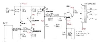
Well, i find it is now using cathode bias about -23V for EL34. I will change it to fixed bias and able to adjust in between -20~40VDC for EL34 or KT88. So that the driver is capable of no less than 50V RMS. And i find the circuit Q3 below showing 72V, I don't know this is you mentioned driver's maximum capability (in RMS) ? If not so, how can i do the simple calculation to find this driver maximum voltage capacity ?
Thanks for your kindly reply. Iwill keep this rule always.
Well, i find it is now using cathode bias about -23V for EL34. I will change it to fixed bias and able to adjust in between -20~40VDC for EL34 or KT88. So that the driver is capable of no less than 50V RMS. And i find the circuit Q3 below showing 72V, I don't know this is you mentioned driver's maximum capability (in RMS) ? If not so, how can i do the simple calculation to find this driver maximum voltage capacity ?
You can find the answer in several ways.
1) draw a loadline for the mosfet or valve you use for driver
2) Simulate the circuit using LTspice
3) Build the circuit on test bench/prototype & measure the result.
This all depends on what test gear you have.
1) needs pencil & paper
2) needs PC A software knowledge
3) needs soldering iron, components, sinewave signal & mete/oscilloscope.
Andy.
The MOSFET is standing 2mA.
The maximum current range is from 0mA to 4mA, but it will not be linear near 0mA, but perhaps will at 0.5mA.
The maximum current swing (in that case) will be 0.5mA to 3.5mA. that has to drive both the 100k Ohm Rg, and the miller effect capacitance of a Triode Wired KT88, much more capacitance than a Beam Power wired mode of a KT88.
Slew voltage at 20kHz?
Calculate and know.

Thanks 6A3 your explain. I will also have the selection for Triode and UL mode connection. Actually, I don’t very understanding how to calculate it, but I just for sure my change should be work and no big deal.
what’s mean of Slew voltage at 20kHz ? Do u mean the capacitance of the valve of the connection mode will affect to 20KHz response ?
what’s mean of Slew voltage at 20kHz ? Do u mean the capacitance of the valve of the connection mode will affect to 20KHz response ?
- Home
- Amplifiers
- Tubes / Valves
- Not sure the circuit can drive KT88