Recently I came across Mark Johnson's thread "VRDN: bipolar regulator PCB for line level ckts: ±11V to ±20V @ 1.5A with "De-Noiser" "
https://www.diyaudio.com/community/...l-ckts-11v-to-20v-1-5a-with-de-noiser.355883/
and instantly became a fan.
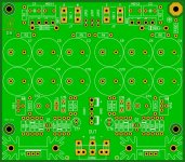
Here is a redraw of his schematic done just for fun. I named it "Butterfly DN". The PCB can be made by hand if you like, it has only two layers.
IT HAS NOT BEEN TESTED YET!
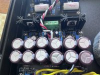
I have ordered some PCBs and will be testing soon.
I will be updating this thread with pictures.
For how to set it up, please visit the first post of the original thread:
https://www.diyaudio.com/community/...l-ckts-11v-to-20v-1-5a-with-de-noiser.355883/
BOM, Part numbering on the PCB and component sizes are exactly the same.
Heat Sink thermal resistance: 6.2C/W - 11.4C/W, depending on the length of the heatsink used (ref. attached pdf)
Board Size: 103,5mm x 91,5mm
Added:
Have fun!
Alexander
Disclaimer
This thread is made by a fan, it is not affiliated in any way to Mark Johnson's work and the original VRDN thread.
This layout is a DIY project done by me, provided "as is", with no official guarantee it will work.
https://www.diyaudio.com/community/...l-ckts-11v-to-20v-1-5a-with-de-noiser.355883/
and instantly became a fan.
Here is a redraw of his schematic done just for fun. I named it "Butterfly DN". The PCB can be made by hand if you like, it has only two layers.
I have ordered some PCBs and will be testing soon.
I will be updating this thread with pictures.
For how to set it up, please visit the first post of the original thread:
https://www.diyaudio.com/community/...l-ckts-11v-to-20v-1-5a-with-de-noiser.355883/
BOM, Part numbering on the PCB and component sizes are exactly the same.
Heat Sink thermal resistance: 6.2C/W - 11.4C/W, depending on the length of the heatsink used (ref. attached pdf)
Board Size: 103,5mm x 91,5mm
Added:
- Optional half rectification diodes D98 & D99 have their own place on the PCB. Remember, they are only used for half rectification, when using a transformer with only ONE secondary. They are marked with a *
- Added an optional resistor (R23, R24) in parallel to every one of the Variable resistors (VR1, VR2), in case you want to replace the Variable resistors by a fixed one.
- 2x Outputs, CON1 and CON2. CON1 supports many readily available connectors. CON2 supports Faston terminals OR Europlug
- Added R100, a way to connect the ground plane to chassis via the top right mounting hole. You can short it or use a resistor 3-10ohm
Have fun!
Alexander
Disclaimer
This thread is made by a fan, it is not affiliated in any way to Mark Johnson's work and the original VRDN thread.
This layout is a DIY project done by me, provided "as is", with no official guarantee it will work.
Attachments
-
sink_e-3082604-2.pdf690.6 KB · Views: 195
-
 IMG_0629.jpg467.7 KB · Views: 299
 -
 IMG_0628.jpg470.9 KB · Views: 302
 -
ButterDN1.5.2_Gerber.zip70.8 KB · Views: 115
-
 ButterDN152_TOP.JPG544.9 KB · Views: 271
 -
 ButterDN152_BOTTOM.JPG355.9 KB · Views: 242
 -
TOP.pdf54 KB · Views: 123
-
Bottom (Mirrored).pdf14.2 KB · Views: 96
Last edited:


")