Looking for some 2SK117, do I even need to buy any?

I have been looking to pick up some 2SK117s for some time, but knowing they are no longer produced, the likelihood of getting fakes are pretty high. I know that things can be faked to make the item look as authentic as possible, but I found this seller out of Japan, has 100% positive feedback, and if he indeed has the original box and such, I would put my money on these being authentic. Does anyone have the same opinion of them?
IMG_1313.jpeg


I’m wondering if I even need them though. I know this is all circuit dependent, so in the end I guess really wouldn’t know. I have at least a couple hundred each 2SK170 and 2SJ74, that I know with absolute certainty are the real thing. In most instances would the 2SK170 be a good sub for the 2SK117? In what instances would it not be a good sub other than circus that use higher than 40 V? Another option I was thinking of was using the SMD part 2SK209, putting it on a small adaptor board. It does have about half the dissipation of the 2SK117 though.

I like having large quantities on hand, especially if things are no longer available, which is why I have a couple hundred each of the 170/74 combo. So I don’t mind buying 200 of the SK117 and if I were to get the 2SK209 I would grab a couple hundred of them as well.

I was hoping to get opinions of others in here. If those 117s do look authentic would it be best if I grabbed those or do you think in 99% of instances the 170 will work? Or with the combo of the 170 and the 209 I should be good to go?

Dan

Stable current-production mosfets for Pimm CCS

I was trying to resurrect some old CCS's boards from long ago for a new headphone amp I'm building, but IRF820's are not too available, or that is to say, the versions available today are quite different in performance to ones from 10+ years ago. So far I've gotten a pretty effective oscillator going in the 600Khz-1Mhz range pretty reliably. They're also pretty hard to troubleshoot because of all the high node impedances that aren't really probe-able even with a good differential without affecting the stability of the circuit.

I've tried a few mosfets to varying success, though all are unstable to various degrees. The closest I've gotten to something working is the FQPF2N80, though I had to increase the upper mosfet gate stopper to 15K and even then at higher voltages and lower currents it still oscillates. I've gone back and tested some of the ones I built 10+ years ago using some FQPF2N60C's, and found though they seemed stable at the time, reducing the current to the 3ma-10ma ranges I need, they also quickly become unstable.

If anyone has had luck with current production/availability mosfets and has a working gate stopper value for them, please share. In the meantime I'm spinning some new test PCB's that have extremely tight loop distances, and one version with mostly SMD parts to see if they show any improvement. The next MOSFET I have my sights on testing is the Vishay IRFIBF20G. I also might explore replacing some of the lower current CCS's (3ma) with simple cascode depletion ones for my project, but I would like to find working enhancement mosfets for these circuits as well because I had some plans for voltage regulators and/or the SS pentode operation modes as well.


Some relevant posts on the topic by Rod Coleman and Gary Pimm:
https://www.diyaudio.com/community/...-bias-ccs-500khz-ringing.318407/#post-5332345
https://www.diyaudio.com/community/...-regulator-projects.82641/page-5#post-1734963

Wayback link to Pimm's original page on the self bias CCS:
https://web.archive.org/web/20110514215841/http://pimmlabs.com/web/self_bias.htm

Does this explain what generates gravity?

Click this for the scientific paper.

This is the Abstract:
Quark movement is almost by the speed of light. Due to this speed their inertial mass-effect increases profoundly. That inertial effect is an accelerating force. Within the nucleon the force is the strong force. As quarks movements are back and forth movements, called zigzag or oscillating movements, there is movement in opposite directions. So the oppositely acting forces annihilate each other. However the force acting on objects receding from each other is a trifle stronger than that acting on objects approaching each other. This small difference between these forces is a “left over” force and “leaks” out of the nucleon. In previous manuscripts, formulae were presented to calculate these forces. In the present paper the “left over”, “leaking” force is estimated, and this force is gravity.
  • Like
Reactions: 2 users

Crossover questions

I own a set of Vandersteen 2Ce Signatures. I just purchased a Vandersteen Model 2W subwoofer on eBay. It has not yet arrived, but I’ve been doing some reading, and it appears that I will need a pair of in-line crossover between the preamp and the sub. Apparently Vandersteen supplied these with the product, but they are now scarce and expensive.

Apparently, the Vandersteen x-overs were variable according to the input impedance of the amplifier. This is confusing to me. Since the sub is self-powered, I would assume that any relationship between the sub's amplifier and the preamp should be handled without an external device. If the amplifier in question is the amp that is powering the main speakers, then I’m also confused – but I’m often wrong. (FWIW, the input impedance of my main amp (PSA BHK 250) is 50K single ended and 100K balanced.)

I happened to notice a set of line of in-line crossovers from Harrison Labs (https://www.hlabs.com/products/crossovers/). The only variable with them seems to be the crossover frequency - not the input impedance of any amp.

I wonder if these crossovers would meet my requirements. Any assistance would be greatly appreciated.

Why i am not getting chest kick? from a 1000w subwoofer (car audio)

I know that midbass is the hardest thing to fix in car audio , but even outside or in house my subs didnt hit, they where just loud af.
i had only 12" subs. Rockford t2 and alpine type x. The t2 was so nice in a small box
Why a 1k sub can't hit you in the chest and a crappy 15" 100w pa driver can?

is Sd my problem? Or is the vas and cms, mms. bl

Now i have an eclipse sw8122, 12" 140gr mms, high cms with 90L vas! 21bl, 500w rms on paper but can do a little more.
Is the same, so is not that. This eclipse is a very efficient sub, qts is 0.3 so the box recommendation is small. Is a nice sq sub

Or is just my taste in old school subs?


(I am buying old subs (only in good shape) because they are cheap, and i can sell them for the same price or more. New subs can be expensive, i am from europe, we dont have cheap good subs brands like in usa)

One BJT line amp/buffer

I need your kind help with one challenge I have. I call it a challenge as I am in disdain and not experienced with BJT-circuits design.

Topic: I would like to use one-BJT (not two or more) for providing a single audio Line Out from many sources Inputs of various output impedance (some are low, some are high) via a switch. Practically it should be a buffer with much larger input impedance than any of the inputs, I softly guess.
Now, comes the hard part of the request:
  • SNR: > 100dB
  • THD @ 0dB: < 80dB for even, and <90dB for odd ones
  • headroom: 14dB (amplitude 5V)

Of course, I could use the switch alone, but the sources are not properly buffered and I am afraid not to mess them up.
The input signal amplitudes are scaled to 1.0V (0dBuRMS)
I have a +18V PS, regulated.
The one-BJT can be NPN or PNP, whichever. I can care less about this.

The first attempt I made it ended lousy: I used a BC547 with CC topology. The output signal has 2-nd harmonic (-40dB) already present even at low amplitudes. At around 0.5V amplitude it started to show huge distortions, both even and odd. Examination show that the positive side are softly compressed, enough to get now ALL harmonics at around -40dB.

Attached the CC-topology I used. The simulations did not show these distortions.
The measured DC voltage on emitter is indeed 8.5V as simulated.

Any hints? What I did wrong?
Is it at all possible to fulfill the above requirements with only one BJT?
Which topology and schematic/components would be better (still one-BJT topic frame)?

P.S. I saw too late that my title is a bit off. This is not a mixer, rather a line buffer. Sorry.

Attachments

  • Screenshot_10.jpg
    Screenshot_10.jpg
    168.3 KB · Views: 587
  • Like
Reactions: 1 user

Looking for crossover component guidance my Carrera build

Hi All,

I'm new here and to DIY audio in general. I've only built speakers so far, and from kits at that. However, for my next project I'm building a pair Paul Carmody's Carreras and I'm looking for a little guidance on crossover components.

I haven't had the opportunity to listen to a lot of different components (only Dayton components so far), but I've been looking around and reading a lot of reviews and specs.
I want good components, but nothing overly crazy. I'd like them to feel "price-appropriate" for the drivers. So I landed on spending roughly the same on each crossover as the pair of drivers in the speaker.

For my first form-schematic build, I'd like to choose 1 particular set of capacitors to build the crossovers with. But I have two competing mindsets on the sound I'm looking for. I really like a big soundstage, but I also like a forgiving sound that won't make music that isn't recorded well unlistenable.

Starting with capacitors, after a lot of reading (this one is particularly useful, this one too), I think I'd like to go with 1 of these 2 sets:
My first question is: Has anyone had any experience with either of these sets of caps and what did you think of them? (and if you've used them in a Carrera build or with either of the drivers, I'd really love to hear from you)

Any feedback is welcome.
Cheers!

noiseless small cooling fan source

There is plethora of choices on Bay but does any of you have a positive experience with any particular fan brand/design ? I need a small unit 3"x3" max to cool down overheating old cd player. I found in my junk drawer brushless 12V /0.18A unit and hooked it up to 5V power supply inside the player and can confirm it's effectiveness but it's way too noisy. It is a pretty old unit so maybe newer designs are quieter.

Open Source Monkey Box

This is a long thread with many twists and dead ends. Before diving in, take a look a this first:
  • The documentation files of the finished Open Source Monkey Coffin loudspeaker. I am (trying to) keep this up to date!
  • The notes at the end of this post, which have some useful hints to navigate the thread.

-----------------------------------------------------------

Following up on the earlier Open Source Speaker thread (part I and part II) I am starting a new thread to discuss the develpment of the "Open Source Monkey Coffin".

Here's an update of my earlier Monkey Coffin ideas. Sorry it's so long.

POINTS OF DEPARTURE (as I see them):
  • The first poll says it should be a three way, and it's okay to cost more than $500 per box.
  • The second poll says that the Monkey Box should be "amplifier friendly" (work well with ACAs or small tube amps, etc.), and it should not be too big (not more than 60-80 L).
  • The speaker should be straight forward to make for DIY novices (we don't want to scare them, we want them to run to the hardware shop and build stuff on their kitchen table). There is no point in designing for expert builders, because they will design their own speakers anyway.

MY IMPLEMENTATION IDEAS (I admit these are partially biased by my own preferences, because I need some motivation to actually put some work into this):
  • The box shoud be easy enough to make on a kitchen table. Dimensions roughly 30 x 65 x 30 cm or so (will depend on the requirements of the drivers and box tuning).
  • For "weak amp compatibility" I set the efficiency target to 92 dB/2.83V/1m, with bass extension to 45 Hz (-3 dB). Achieving this will not be very easy.
  • The impedance curve should be flatish and qualify as "8 Ohm". This means we can't "cheat" with the efficiency target by using low-impedance drivers.
  • Use high-quality drivers/parts with the right tech specs for the task. The look of the drivers has to be "right" for a HiFi system in a home environment, but is second priority after the tech specs (people may not want to build a speaker that does not look "right").
  • Woofer: The woofer will likely be the limiting factor that determines the size/bass-extension/efficiency compromise. I guess a 10" unit would be the right choice here. The earlier threads already mentioned a few units that might be interesting for this design (Fane Sovereign Pro 10-300SC, Ciare FXE 10-2.5, Volt BM251.3, some Beymas, etc.). We'll have to look at this some more.
  • Midrange: Needs to keep up with the SPL requirements, so many of the conventional "HiFi" midranges are out. I have some experience with the ATC SM75-150 dome, which is VERY good, expensive, and not available to DIYers anymore. When ATC stopped selling to the DIY market, Volt released the VM752 dome, which is a very good clone of the ATC driver. I really want to use the Volt VM752 dome. It can be used from its fs (400 Hz) up to about 3 kHz or so.
  • Tweeter: There are many good tweeters out there. I am a big fan of Be dome tweeters (ScanSpeak D3004/6640, SB Acoustics Satori TW29BN). I also read a bit about waveguides, which do good things. They help with matching the dispersion of the tweeter to the midrange, they reduce the effects of baffle diffraction, they increase the on-axis efficiency, and they reduce non-linear distortion of the tweeter (by reducing the drive voltage for a given SPL). At the moment I can't think of a reason why we should not use a waveguide.
  • Cross over filters: the x-over frequencies will depend quite a bit on the driver choices. However, if possible, I like to set the woofer/midrange x-over frequency such that it fits the baffle-step centre frequency. This makes it easier to compensate the baffle step by fiddling with the woofer SPL vs midrange SPL. If the drivers allow, I like using 6 dB/octave filters because it's easier to get the time-domain response of the loudspeaker right. In my experiments, my ears preferred 6 dB filters over 12 dB filters.
  • I will openly admit that costs are not my first priority. If the right parts cost a lot of money and there are no alternatives, so be it. The earlier threads indicated that it's ok if the parts cost is more than $500 per speaker. Some said $1000. My priority is to make this a very good speaker, and suitable parts may cost a bit of money. In the end, there will always be substantial flexibility with costs related to x-over parts and enclosure materials + finishing.

NEXT STEPS AND QUESTIONS (everyone has his/her own approach to loudspeaker design, but here's my suggestion):
  • In the first step we'll have to narrow down the driver choices. This will be a forward-and-backward process between driver suggestions and model runs using these drivers, always keeping the design targets in mind. I'd suggest choosing a woofer first, because that will define the box size, bass extension, and sensitivity. Let's say the midrange is set (yes, you are allowed to complain, but... :mallet:). The tweeter comes last.
    Question: What input data do we need for these model runs? Do we need actual measurements of the drivers in their baffle/box? I am not big with modelling tools, and I tend to replace detailed model runs by measurements from prototypes. Others might be more efficient than this by using their modelling tools.
  • The second step is to build an actual prototype. Now we need money to buy parts. If the design is still attractive to me (i.e., it's something that I'd like to build and use myself), I'd be willing to put in some money and go for it. I could also do measurements.
    Question: How will the funding work? Anyone experienced with raising and managing money for open source projects? Anyone willing to put some cash on the table? Who will manage the money, and how?
  • The third step is to tweak the prototype. Again, this will be another forward-and-backward process. And we may need more money.


---------------------------------------------

Notes and updates:


Important note 31 Oct. 2019: DIYers may profit from this open-source project for their own private purposes, for example by building and enjoying a copy of the Open Source Monkey Coffin speaker. Please do not use the information developed in this open source project on a larger scale (for example by selling speakers based on the Open Source Monkey Coffin design or substantial parts of it) without written permission.

Note 4 Oct. 2018: This project has received financial support from LORDSANSUI, Paul Vancluysen, George Wright, KaffiMann, Charles Bueche, zimmer64, John Barbor, and others (anonymous) here. Thank you!

Note 10 Nov. 2019: This project has come a very long way, and the OSMC design is now completed. The design goals have been largely met, but some of the early implementation ideas have changed a bit along the way (x-over topology, woofer size, tweeter details). The full documentation of the OSMC design is here: https://github.com/mbrennwa/osmcdoc

Note 4 Oct. 2018 and 18 Nov. 2019: Final choice of drivers:
  • Tweeter: ScanSpeak R2904/7000 ring radiator (post 295 and follow ups) with a custom waveguide as described in post 881 (available via group buy or by DIY 3D printing or CNC machining).
  • Midrange: Volt VM752 3" textile dome
  • Woofer: FaitalPRO 12PR320 12" paper cone (see post 162 and post 244).

Note 18 Nov. 2019: Final enclosure is in post 925 (drawings) and post 930 (photos, showing stuffing).

Note 18 Nov. 2019: Final x-over is in post 931.

Note 18 Nov. 2019: The polar response diagrams (horizontal and vertical) are in post 895.

Note 18 Nov. 2019: The power response is in post 901.

Note 18 Nov. 2019: The electrical impedance is in post 900.

Note 19 Feb. 2020: A bunch of graphs with test results as compiled from the documentation on GitHub (on-axis SPL response, step response, polar response, cumulative decay spectrum (CSD) are in post 917.

Note 9 May 2020: If you don't know where to look, here's a list with some shops and retailers for OSMC parts:
  • diyAudio group buy for the OSMC tweeter waveguides
  • Falcon (Europe): Scan 2904 tweeter, Volt VM752 midrange driver, x-over parts, etc.
  • Solen (Canada, US): Scan 2904 tweeter, Volt VM752 midrange driver, x-over parts, etc.
  • Audiohobby (free shipping everywhere!?): Scan 2904 tweeter, x-over parts, bass-reflex ports
  • US Speaker (US): Faital 12PR320 woofer
  • Blue Aran (Europe): Faital 12PR320 woofer
  • Acoustical Surfaces (US): Melamine foam. Contact person: Tom Ewert +1 (952) 466-8229. They also sell in small quantities!
  • Ebay: Melamine foam
  • Buttinette (yes...): lambs wool
  • Deer Creek Audio: Custom speaker stands

Pearl 3 Burning Amp 2023

Here is a PDF of of the Pearl 3 from Burning amp 2023 for those of you whom already have circuit boards.


Pearl3_BA2023.jpg


EDIT: Video presentation on Pearl 3 for BAF '23 can be found here - https://burningampfestival.com/videos/


EDIT: Build documentation "Pearl 3 Phono Build Doc-1.0c" is attached below. Version 1.0c is the most current. Download and print.


EDIT: Interview with Wayne about Pearl 3 - #881

EDIT: Modushop/ HiFi200 Chassis set available here - https://www.diyaudio.com/community/threads/pearl-3-burning-amp-2023.404054/post-7538807 https://modushop.biz/site/index.php?route=product/product&product_id=971

EDIT: Online build guide - https://guides.diyaudio.com/Guide/Pearl+3/28

EDIT: SMD soldering tutorial using Pearl 3 - Login to view embedded media

Attachments

  • Pearl3_BA2023.pdf
    123.7 KB · Views: 2,061
  • Pearl 3 Phono Build Doc-1.0c.pdf
    1.3 MB · Views: 1,050
  • Like
  • Thank You
Reactions: 39 users

Giveaway PCBs and pucks for Warbler

Seems not so many specimens of this one around here. ZM tested one don’t know if he still has it and then me 🙂

Practically this is A Big Mofo on steroids.

complete amp.jpg


What about giving birth to another one? Are there any FABs left around?

I am giving away a pair of empty pcbs for the amp, a pair of empty pcbs for the power supply and a pair of ixfn280n085 pucks.

pcb.jpg


1.If you consider you are a FAB you will still need a power supply that can give 26-32v/3.5a for each channel, preferably a 36v 200w smps from meanwell for each channel. I recommend the 36v one, lrs-200-36 which can be adjusted for 32-33V on the output.
2. You will need an inductor that can support the bias current which is set between 3-3.5a so a 4a inductor preferably for each channel. I got mine very cheap from www.Ogonowski.eu
3. You will need a heatsink with a thermal resistance of 0.2C/W at maximum for each channel so a 5u deluxe enclosure for both channels or something smaller force cooled.
4. You will need also a preamp that can swing 20Vpk no matter if it’s a high output impedance valve one, the amp has a high enough input impedance to handle all of them.
5. You will need also all the parts in the BOM.
6. And last but not the least.. you are comfortable soldering smd parts.

Instead of the puck mosfet you can use as gain device a sit like thf51s or the 2sk182es.

Here are the schematics

For the amp
sch amp.jpg


And for the psu
sch psu.jpg


So if you are sure you are going to build this amp make a second thought and if still sure put your name in the list.

How it'll work:
To enter, just copy the list of entrants, paste into a new comment, add your DIYA username to the bottom of that list and post. Tuesday night I'll make a comment saying that entries are closed. I'll take the final list of entrants, paste them into an online randomizer, and the name that appears in the top (#1) position will be the winner.
Because this is a serious build and I don`t want that the boards will be stashed instead of being used, the winner will need to post some pics with one of the requested items at points 1-4. So if you have a pair of lrs-200-36 or a pair of inductors or the heatsinks or the preamp you are good to go.


Good luck!
  • Like
  • Thank You
Reactions: 9 users

Problems with air speed in ducts (WinISD)

I'm designing a box for an 8" woofer, when I see the air speed graphs in the ducts it's always absurd values and when I fix the duct it's more than a meter in size
What frequency do you recommend for this box? I tried co, 30, 35 and 43.49 Hz
Here are my woofer settings
I tried to make it work in a sealed box so the spl disparity between the sealed and ducted box really discouraged me, as the midrange has a very high spl in comparison.
1717201493920.png

1717201522202.png

1717201594281.png

Attachments

  • Bomber.pdf
    423.9 KB · Views: 12

Some new buys Garage sale stuff

I picked up a couple today. One pair is a home made set using cheap Jaycar drivers but the other set is some old Tandy
Optimus 5-B / # 40-2006
I hope they are the ones I want with the twin 16R tweeters doing the midrange and a singleton working up higher
Anybody here have any experience with them before I pull the drivers out and check the boxes. One thing tho; these are quite heavy and do appear to be both e=well constructed and in reasonable condition

Attachments

  • IMG_2999.JPG
    IMG_2999.JPG
    101.2 KB · Views: 31
  • IMG_3000.JPG
    IMG_3000.JPG
    85.5 KB · Views: 30

The Incredible Technics SP-10 Thread

EDIT: (many years later...)

Putting a couple amazing links here in the top so members can better find them;

Mike Barney's page, which in my opinion is the best single SP-10 page out there -
https://sites.google.com/site/mpbarneysources/sp-10-mk2-pro

A great rebuild thread on AK -
https://audiokarma.org/forums/index.php?threads/technics-sp-10mkii-restoring-an-icon.900468/

JP's storefront -
https://fidelisanalog.com


Amazing SP-10 content here -

https://www.theanalogdept.com/sp10-gal.html


SP-10_first_photo.jpg

(The funny widgets are the motor hub fixing plates)

No, you are not seeing double.

This is my newest and most ambitious project yet - Technics SP-10Mk2A. Neither have a PSU, but that's not a difficult thing. Happily, both are operational, I tested them today with a friend's PSU. One has a fiddly main switch. Both are in sorrier cosmetic shape than I thought. That may prove an issue, only time will tell.

So will I make one good one from the ashes of two? I have no idea yet. Of course, having two at the end of this is always more attractive of an option. I do, however, think I may make one black, that would look quite sharp.

On the to-do list -

Re-cap the main board.
Build PSU
Adjust main board and switches as needed.
Figure out if I have one good table or two.
Build plinth(s).
Address cosmetic issues.
Determine if I can get a long armwand for my Graham, or just get a 10.5" Jelco.
Etc...


So let's get started --


Like I mentioned, both tables are operative, the biggest concerns (other than the need to build PSUs for both) is purely cosmetic.

So let's look at the tables as I received them. These photos intentionally are showing all the warts as ugly as possible.

IMG_0547.jpg

The prettier one. Not bad generally, but the marring and corrosion is all on the 'close' side of the table where it will be seen.

IMG_05501.jpg

The text can be re-filled. the corrosion is fairly shallow.

IMG_0549.jpg


IMG_0548.jpg


IMG_0551.jpg

A couple of nicks in the black paint. No big deal.

IMG_05551.jpg

Marring on the paint, no corrosion.

IMG_0553.jpg

Inside the brake section is very clean, and there is plenty of friction material (felt) on the band.

IMG_0554.jpg

I have no idea if this is a lot of wear or not on the hub. I thought it worth a photo, to see if anybody can compare.

IMG_0563.jpg

The platter of the prettier one.

IMG_0564.jpg

A bit of corrosion, nothing severe at all.

IMG_0561.jpg

The stock platter mat had something glued to it. I have no idea hot to get a hard adhesive residue removed from rubber...

IMG_0562.jpg

USSA-5 Build with Review

USSA-5 build and review:

Amplifier Design/layout: Fab (The Great and Powerful Ape)

Amplifer PCB Layout: Alex

PSU Design/Layout: Project16

PSU PCB Production: Prasi


I couldn't stop thinking about this amplifier. The obsession began with a few fleeting traces of it's existence. The few members that have actually completed it were mostly silenced by its greatness. When I had enquired about it, people simply said "Oh, the USSA-5? It's the best amp I've ever heard."

I had to build it. But, the great mind that designed the amp wasn't going to just give me the boards. I offered to build a children's wing at his nearest hospital in his name. He said no. I said I would make huge donations to wildlife preserves around the world. He still said no. He was like talking to Willy Wonka and I was Charlie Bucket. I needed a golden ticket....

In the end, what worked was honesty and a promise to do two things: to build the amplifier and write a review.

So, here it is.

2A3 monoblock chassis size question

Laid this out for 12x8x2. GZ34 top left, PT to right, Lundahl 1673 choke, 6SL7 center right, 2A3 bottom left, Hashimoto H-20-7U to right.

2” height should be enough room for internal components. I’m not using those polish paper-wrapped capacitors, so the electrolytics are under 35mm diameter.

I figure input in the back, shielded into 1st stage, RCA jack to front SIDE - this will be for RIGHT channel, left channel will be mirror image.

From experiences with other amps (Tektron 2A3/50IS/300b and a homebuilt 300b, it doesn’t get THAT warm inside to worry about, but I’ll leave some space around the sockets for air flow.

Any suggestions about placement, spacing? Go with a 16x8 or 17x10?

Thanks in advance.

Norm

Attachments

  • IMG_8807.jpeg
    IMG_8807.jpeg
    394.6 KB · Views: 73
  • IMG_8806.jpeg
    IMG_8806.jpeg
    430.9 KB · Views: 74

For Sale MarkAudio Alpair 7MS Pair, MarkAudio CHR90 Pair, SB Audience Satori MR13P, Seas ER18RNX, Visaton, All New

Selling the following drivers:

1 Single SB Audience Satori MR13P-4 Neodymium Paper Driver -- $60
1 Pair Visaton GF200 Woofers New -- Sold
1 Pair Seas Prestige ER18RNX -- Sold
1 Pair MarkAudio Alpair 7MS -- Sold
1 Pair MarkAudio CHR 90 -- Sold

-Lot 1 https://www.ebay.com/itm/276465785384
-Lot 2 https://www.ebay.com/itm/276465775796

All drivers are new. Price does not include shipping costs.

DHT Headphone amp for HifiMan Edition XS

I'm looking for ideas/suggestions to make a diy DHT Headphone amp for HifiMan Edition XS.

Specs
Frequency response : 8Hz-50kHz
Impedance : 18Ω
Sensitivity : 92dB

Salas advice: "Needs custom opt ratio and 1W audio power at least", I guess after the output transformer.

To make a budget proto I want to use not too expensive tubes so russian 6C4C/6S4S (2A3 equivalent) or 4P1L or similars

TIA
Felipe

Attachments

  • HifiMan Edition XS.jpg
    HifiMan Edition XS.jpg
    323.7 KB · Views: 38

Accuphase P-7100 Amplifier Clone

Hi. I'm starting this new thread about my Accuphase P-7100 amplifier clone. Most of the owrk is already done, and I just completed both amplifier module last week.
I tested and preset both amp modules today and everything is looking good. I pre-set the bias at 5mV on the final instead of the specs 20mv (20mv / 2x 0.47R = 21ma / Transistors
The front end and Meter/Softstart/Protection PCB are tested and working fine. The main +/-75V Power supply is already assembled on the chassis. It is made of a massive recycled Rotel potted power transformer, two large 51,000uF/100V Kemet power capacitor, as the original just one 35MB100A, 35A, 1kV rectifier bridge and a copper GND bus bar as the original.

I'm trying to emulate as far as possible the original, since I know the Accuphase sound and love it. I went throught the service manual and decoded the detailled BOM that list all the type of resistors and caps used where (film, carbon, MOX, carbon film, and as far as possible the same caps series and type).

The PCB, original clone of very good quality (2mm, gold plated) are from ebay. All the pcb were replica of the original and match the service manual schematic, except the Meter/Softstart/Protection PCB. The original processor amp control was replace with discrete circuit, and the usual uPC1237 protection IC, but there was no info on it, and no part values. I had to find the circuit and test my mods by myself. The input stage pcb is the same circuit but the parts ID are different from the original schematic, and some small differences are there as well. I documented the changes and wire the board accordingly. Chassis is a clone from Aliexpress.

The original amp section used 2SC5358/2SA1986 (230/15A), me I'm using the 2SC5200/2SA1943 (same 230/15A) that I bought years ago, and match them myself.
I used thermal spread aluminum bars to mount the power amp transistors, and to add rigidity to the clone heatsink made of two section. The output amp module is now solid as a brick. The amp pcb also inclded nice brass bus bar and input transistor pairs rubber caps, as the original.

Here some pictures of the PCB. There are some extra PCB such as the rectifier PCB and Softstart and Ground Lift PCB.

Attachments

  • Various PCB.jpg
    Various PCB.jpg
    206.2 KB · Views: 198
  • Meter-Softstart-Protection PCB.jpg
    Meter-Softstart-Protection PCB.jpg
    216.9 KB · Views: 209
  • Final PCB (2).jpg
    Final PCB (2).jpg
    247.3 KB · Views: 215
  • IMG_20220204_132300.jpg
    IMG_20220204_132300.jpg
    299.9 KB · Views: 209
  • IMG_20220204_132307.jpg
    IMG_20220204_132307.jpg
    339.1 KB · Views: 168
  • Like
Reactions: 5 users

Looking for transformer recommendations, Aikido octal

Hello all, can any on this site recommend a power transformer for my new build? I want to use the Aikido octal board and the PS tube kit with the 5y3 rectifier tube. the 270cax from Hammond is recommended on the glassware audio site, but I don't know if it's a good match for the octal board....I have also heard of set ups with 2 transformers. 1 for the heaters and separte for the B+

STM32 USB to I2S multi channel - log - ask for help

***** 03/03/2024 Update of project scope => move from UAC1 to UAC2 ******

Hello,

I'm putting on the bench someting in my head since a long time, that should not be too difficult to achieve for ones with know how... but could not be as easy for me ;-)

I want to program a "simple" USB to I2S, 8 channel device, UAC2, single sampling rate (48kHz or 44.1kHz), with Asynchronous mode.

Why UAC1: because ST proposes some UAC1 libraries, and no UAC2 ones (at least officially). UAC1 works without drivers on Windows and Linux.

SB Full Speed (FS) allows for 8x 48kHz x 1- bits (or 4x 48kHz x 24 bits). Great Monitor studios like Neumann KH150 have internal single 48kHz sampling rate. Many people consider that CD quality is "sufficient" and don't race for more bits, more Hertz. It is easy to find stm32 boards with USB FS, and more difficult with USB HS.

This would aim at providing the connectivity part to a 8ch DAC like ES9080 or AK4458. Overall target is 100% function and 99.5% performance of top products. for that niche need of multichannel. It could pair with RPi / Linux DSP offers like CamillaDSP for active speakers (or speakers / subwoofers combos...).

Plaform is a STM32F4 dicovery board to start with, then could be a STM32 black pill (seems to fit the purpose), which pave the way to dedicated board if needed. Those platforms unfortunatly have SAI, but if done well, the different I2S peripherals can be synchonized as slaves from a master, or all slaves from an external clock. A blackpill could be the USB "module" of a DAC board.

I would be happy if the the code could rely "as much as possible" on HAL libraries, code generated by STM32CubeIDE, and ST USB middleware. But, why did they made that so complex, with so much abstractions, while still needing to dig in all "layers" to fit/finalize code, and not really robust... I reallydon't like it so much, and it does not looks nice to me. But it should ease future portability (at least try to).

Intention is Open Source for the application part (not an expert about ST "mixed" licence for the USB stack but should be OK for DIY community).

Oh, if it already exists on Github or elsewhere, and I have not found it: let me know. I will be super happy ;-)

Current understanding is that, based on existing stereo code, I only need to:
  • find all locations where the number of channels impacts the code
  • change the nuber of channels from 2 to 8,
  • ensure the consistency of the buffer size,
  • on periodic basis, slit the 4x2 channels in sequence from the inputs to 4 distinct buffers that will each drive an I2S (through DMA)
Help of people knolageable about USB UAC and STM32 will accept to help... and I may have stupid questions.

I have an almost working stereo code based on ST examples. I have a first version that declares 6 channels, which is not working. I will come tomorrow with some questions...

Go :)

JMF

How good was the KEF B200?

The Kef B200 was in loads of speakers around the 1980s, and there still seems to be a few about.

Rubber surround so no foam to rot.

So the question is "how good is it"? Is it worth using for a 2-way speaker project, either sealed or ported?

Is it still competitive or are there better 8" drivers available these days?

The SP1014 is the common one with the smaller magnet. Are the larger magnets any better, like SP1039?

And I gather the crossover needs to be 3K or below, but I haven't seen any frequency responses for the B200.

So - worth using or pass?
  • Like
Reactions: 1 user

Looking for a vector network analyzer for audio circuits

Hello everybody!

I am looking for a vector network analyzer that can measure audio signals (20kHz down to 20Hz).
I know that the "best" solution would be just using the soundcard from the computer and some software but I want a standalone device.

I already searched online but I only either found audio analyzers that would just analyze a incoming signal (no built in signal generator) or I would find vector network analyzers that worked from 9kHz to a few GHz.
But I want an actual VNA for audio frequencies.

Can anybody recommend me anything?

"WHAMMY" Pass DIY headphone amp guide

EDIT DEC 2021 - There are a huge amount of lost photos in this thread, please go to this link to see the new guide:
https://guides.diyaudio.com/Guide/WHAMMY+headphone+amplifier/3?lang=en


Wayne's
Headphone
Amplifier
Must
Make
Yourself

Yes, it's a silly name. But it's cute. And it explains a lot about it. So it stuck.


Video of Wayne talking about the Whammy at BAF 2017 -- Wayne Colburn at BAF '17

PCB available here - WHAMMY Headphone Amplifier – diyAudio Store

Given the explosion in the popularity of headphones, as well as the unbelievable amount of choice and variety in the market, it seemed that a simple and great-sounding headphone amp would be a great addition to the DIY community.

This one will drive any headphone you want to throw at it. Wayne wanted a headphone amp for his desk. This is the fruits of that idea. It’s made to be made in an afternoon or an evening and it has no adjustments, it’s going to have a high likleyhood of success for the builders. :)

It's an all in one PCB, just wire the AC & fuse, input and output jacks. Add a selector switch if you like.

Class-A output stage with enough current to drive anything. It also makes a good linestage with about 14db of gain.


PSU

Transformer 15VA or 25VA 15+15 to 22+22

25VA 22V+22V is best and used in this guide.

Currently the transformers that fit the board are available at Digikey
Amgis 6663, 6664 / Amveco 70053

Here's a link to a factory surplus transformer that fit the PCB will work beautifully - You will want to make R16, R22, R29, R32 15ohm if using this transformer.

70054K PC Mount Transformer 110/230V-18/36V 110V-36V 110V-18V 230V-18V 230V-36V

There are pads on the PCB for a non-PC mount transformer if you have room in your chassis. Something like an Antek AN-0220 or AN-0222 would work well. AN-0220 - 25VA 20V Transformer - AnTek Products Corp

If you use smaller transformer you may need to adjust the bias down a bit. It will still be pure class-A for 99.999999999% of all headphone listening.


The bridge is made from 1N4004 or use high speed diode if you like. Snubber capacitor C20 0.22uF 250v X-rated.

AC filtering is done in a big and effective way, utilizing a CRCRC filter with 3300uF capacitors and 5.1ohm resistors. You can use smaller resistors and caps if you like, it's a very effective filter and will work well with even 1/2 the values.

The regulators using 7815/7915 can be elevated a bit, using a red or green LED as the reference if you wish. Don’t use blue, they are noisy and they will set the regulators to too high of a voltage.

Circuit

On the input there is a dual opamp used for voltage gain. We’ve tried these with great success LM833, Muses 8820, RC4580, OPA2604, AD823, TL072.

If you want to try a different opamp, try something made for audio. Feel free to try some surface-mount opamps in a DIP adaptor if you like, there are lots of neat opamps to try.

Gain is set by R8/R12. Lower gain, make R12 bigger, unity gain, R12=10K

Potentiometer - Alps RK27 fits the PCB, feel free to use what you like. If you have room in your chassis, this is a fine place for a stepped attenuator.

After the opamp there is a Mosfet source follower for current capibility, and the feedback loop includeds the opamp. This keeps the DC offset stable as well as lowers the output impedance to a very low level, less than 1/10 of an ohm.


Output stage

The output stage is a Mosfet NP pair in source-follower configuration. Being a follower it can add no voltage to the signal but can contribute lots of current. Since the opamp os being used for gain this is not problem. It also has the advantage of adding very little sonic flavor to the signal, it's esentally transparent. The output stage is simple, powerful, will drive anything, and is self adjusting due to optocoupler and the opamp controls DC offset because the output stage is in the feedback loop. No potentiometers to adjust or voltages to read when biasing.

Output impedance is less than 1/10 ohm

The following Mosfets work well in the circuit.

Toshiba Mosfet 2SK2013 / 2SJ313
Fairchild Mosfet On Semiconductor Fairchild FQP3N30 / FQP3P20
IRF Mosfet Vishay IRF610PBF / IRF9610PBF

No matching is required.

Bias arrangement (low offset due to opamp precision)

(4) 10K resistors make a voltage divider to give lots of bias voltage to the gates; this bias will be 1/2 the rail voltage. Assuming a standard build with 17v rails this will give the Mosfets a maximum of 8.5v of bias. With no other controls his would make the output devices conduct like there’s no tomorrow, and probably let the smoke out, but the 4N35 optocoupler helps control and set the necessary bias voltage. With this it happily operates in Class-A all the time.

The 4N35 optocoupler does a few things -

The optocoupler has two sides when looking at the schematic, the diode and the transistor. They are linked optically, not electrically, so the two sides of the optocoupler can share different voltages that don't effect the other side. as the current change in the LED side of the opto it will glow brighter or dimmer, which controls how much the transistor side conducts - in this circuit the current through the LED is directly equal to the mosfet current, and as it gets brighter it controls the BJT, whereby the BJT "burns up" the excess dc bias voltage.

The optocoupler appears to be a variable resistor in parallel with the inside 10k resistors - it changes the gate bias with the collector-emitter junction as the opto coupler looks at the current through the mosfet sources. The LED part of the opto has a 1.2v constant drop, this is used in conjunction with R18 to set bias current across the source resistors. If the current is too high it will make the LED brighter, that modulates the base of the transistor, and the collector-emitter junction will decrease its apparent resistance in parallel with the inside 10k resistors, changing the ratio of rail voltage to ground, decreasing the amount of voltage on the gates, and keeping the bias stable as the load swings.

Is a simple solution - its a single part and it automatically adjusts. If there is any drift the optocoupler will compensate immediately No resistors to measure across and potentiometers to adjust

Output bias

The diode in the 4N35 gives voltage across source resistors to set current, a 1.2V reference.
Total source R is added, so 10R resistors is 1.2V/20R=60mA
Want more bias? make the resistors smaller. 4.7R = 120mA
  • Like
Reactions: 1 user

Caladan by Clayton Shaw DIY

Inspired by New Record Day video about the Caladan by Clayton Shaw, I decided to do it DYI since shipping costs to Japan are ridiculous (and no international deliveries at the moment provided). My MiniDSP serves as an active crossover for two ICEPower 125ASX2 amplifiers. They sound amazing, using a Linkwitz-Riley filter 48db at 1kHz and some gain in the low end, Never thought open baffle speaker can have such a lot of low end, while the speaker membrane is barely moving. The speaker disapear and you feel like in a live concert. This works also for my music with distorted guitars, not only for the high end demo music. Bass guitars sound so real. This is the first day listening to them after waiting 3months for the delivery of the 12inch speaker drivers....I guess no burn in needed. Clayton Shaw chose the perfect drivers.....
DIY Caladan.jpeg
  • Like
Reactions: 5 users

Help me understand electromagnetic and electrical field strength and safety.

Hi all,

There are a few questions I’m looking to get answers for relating to safety and electrical fields

1. What are the risks associated with typical electrical fields found in homes and business? There may be cases in commercial business or properties where these risks are reduced for many reasons not necessarily related to perceived health concerns? Some industrial or electrical power supply business will have specific practices to address very real safety concerns. What are the reasonable steps or mitigations that can be applied to residential properties either in established building codes or that can be performed by owner or occupier?

2. Is EMF measured in current per metre squared and what is the difference between emf and the electrical potential in free space measured in volts per square meter? What are the safe limits for frequencies in the related to appliances ( not wifi Bluetooth 5G etc).

3. While EMF from appliances is generally regarded as ‘safe’ there are those that claim to be sensitive. While there are various videos on you tube with cheap hand held meters, I have read that these are not particularly accurate at the frequency ranges that may be associated with fields generated from appliances. ‘Do I have to be worried’ about electrical fields in the house wiring or is the real concern proper grounding of appliances that are supposed to be grounded?

Login to view embedded media
https://www.healthline.com/health/emf

4.Do we unknowingly put our selves at risk through poor design? Or a lack of the ability to determine the risk due to the background noise of life’s other risks and dangers? Lead dress and component layout can have a significant effect on the performance of a boutique or high end amplifier. Are ‘cheaply built’ houses filled with always on appliances electrical nightmares that can affect your experience of life or health with out you knowing why?

Login to view embedded media
I am not wearing a tinfoil hat but can go to the kitchen and make one if the brains trust recommends 🤔

The Omnipressor

Has anyone heard of the Eventide Omnipressor? I'm curious because it could make for an interesting compressor discussion but I'm not sure what Forum it belongs in. I reverse engineered Walter Becker's personal unit and built my own version and demonstrated it for one of Walter/Donald's producer friends and he liked it better than Walters. It was fun to take a deep dive into such a weird compressor.

becker-omnipressor.jpg
This also gets into a discussion about VCAs and I find that pretty interesting too.

Scratching my Brain trying to remember a tube type...

I am trying to remember the number of a regulator triode, which is essentially half of a 6528 on a smaller base - but I can't remember if it was magnovial, 9 pin miniature or what.... it's a graphite plate tube, very similar construction to the whole family of 6as7/6336/6528....

So, I have found the 7233, but I know that's not it - as what I'm looking for has a slightly higher mu, and I remember much higher gm, like twice the 7233... like the difference between 6336 and 6528. It is to 6528 what 7233 is to 6336.... I wish I would have bought some years ago whenever I was pondering them, but it seems I did not, after rifling through my shelves a couple times over....

Anybody know what I'm on about? I'm just gonna have to go through data sheets one by one, lawd have mercy... and the thing is - it might be a soviet tube... sigh...

tunable gain preamp

hi everyone.
instead of using a fixed high gain electronic module (whatever the technology) and an attenuation pot (whatever the technology) , why not have a preamp circuit that exhibits from the start the exact gain needed according to the source output level, amp sensitivity and listening level chosen ?
For instance, with today's sources and amps and at usual listening level, you often need a say 0dB gain preamp so your common and possibly very expensive 20dB line preamp has -20db of attenuation in front or in tail. Not the shortest road ... As we say in French : "Quand le tabouret est trop bas, on coupe les pieds du piano". By the way, most line preamp designs have in reality an enormous gain that is reduced to around 10 by the use of negative feedback.
Here is a three BJT tunable gain preamp -very messy- prototype that gives 20dB of max gain, very large bandwidth and very decent output impedance. No feedback used, no regulated PSU but cross wired double choke on balanced bipolar PS and by design very low power power trans instead (definitely not the modern trend !), among other things.
Considering the very encouraging sonic results, I believe the idea is worth digging.

preamp 01.jpg
  • Like
Reactions: 1 user

4-way instead of 3-way?

Hi experts,

I'd like to put my thought or plan or whatever to get experts' advices on it.

I have been thinking of a new 3-way speakers around the same ATC SCM75-150s, complemented with Scanspeak D2104 21mm tweeters and some 8" double woofer instead of a 10" Volt B2500.1.
Then I was invited by another DIYer for auditioning his new speakers using Raal 70-20 tweeters, Scanspeak's freakin' expensive 83mm dome midrange, also Scanspeak's illuminator 7" as a midbass, along with Scanspeak's 13" woofer. He originally planned a 3-way without the midbass, but got an advice from a professional to add the midbass in between. It sounded awesome, and also seem to prove the superiority of the 4-way design.

So, I began to wonder what if I add midbass between ATC and 8" double woofers. My logical half tells me professionals and experts will say midbass is not necessary with 8" double woofer below. But I am still curious. What are your thoughts about this?

Regards,
Jay

DIY midtweeter planar, physically curved and shaded to be used in a dipole CBT

Thanks to all the amazing help I got in my first thread musing about flexible PCBs (and why not to do it) I decided to scrap my requirements and start again.

My new requirements are:
  1. Single planar driver, 160 cm tall.
  2. Good frequency response, no ugly dipole peak allowed.
  3. Physically curved with a 75 cm radius.
  4. Shadeable, ideally as an internal part of the coils but splitting the coils into multiple separate parts that can be driven separately would be OK.
  5. Can cover from 300-400 hz (24 dB / oct crossover) up to 20 khz.
  6. Can output 100 dB @ 1m across the operating frequency range without too much distortion.
  7. Comparable horizontal dispersion to a Neo3W, limits horizontal radiating area to ~ 35-40 mm wide in the treble.
  8. Should behave as a single driver with vertical CTC of at most 2 cm. I want to avoid vertical lobing.
  9. Manifacturable with a 3d printer + using laser cut plywood.

Basically I want the perfect purpose build planar driver for my new dipole CBT which will look very similar to the old one :) but with a planar as the main driver instead of full range 2.5"cone drivers. I'll still use cone drivers for 80-400 hz but I'm planning to hide them behind the planar in the spine of the speaker.

I will at least initially use 12 micron mylar & 30 micron aluminum foil. I will cut the foil on a silhouette cameo 4. I think I will need ~ 1 mm clearance between traces of the coil but I'll have to test that when I get parts & the machine. But since others here on the forum has done this already I'm not that worried and it will probably work just fine.

I also have plans to Corrugate the membrane lengtwise like this to stiffen side-to-side resonances. And then mount it top and bottom while floating (with foam) at the sides to reduce resonance frequency.

There are lots of small desicions I need to but for now the next open question is:

How should I setup my magnets?​

I'm tossing around ideas for 4 configurations. Since I like tinkering I might just build all 4 and then measure them and see which one I like the best.

The 3 lengthwise setups are pretty normal. Just a question of how big the gap between the magnets can be without it impacting performance. My gut says that of course the 7 magnet setup will measure better in the treble but how much better and would it be significant? Having only 3 rows of larger magnets would probably be much easier to build. Since I wont have a metal front plate I'd have to get creative making a strong enough frame that I can print. But should be solvable although I might need to add more frame around the magnets to help support them.

The magnet-sideways mounted setup is kinda weird but would have some distinct advantages: It would be easier for me to manifacture on my 3d printer while at the same time having less support since I can rely on the magnets themselves for mechanical support. It would also probably measure extremely smooth in the vertical axis since it is extremely uniform thus should have an effective minimal CTC.

It does have some glaring disadvantages though: I'd have to come with some way to ensure that all the magnets and the coils are in alignment which isn't a trivial problem to fix. I'd also have to get creative when corrugating the membrane since all the corrugations would need to be uniform along the whole length. Also, it would be slightly less efficient due to the coil twisting more. It would, however, be fun to try to overcome the engineering challenges and build it anyway :LOL:

MagnetMusings.png


Next step​


First is waiting for materials but then plan to build and test prototypes. My plan is to build 20 cm tall prototypes since the main thing I want to test is how the different setups perform in the horizontal axis + how easy they are to manifacture and how mechanically stable they are. Or basically how much extra support do I have to add to make it not fall apart, less is better.

The design which measures good enough while also being easy enough to manifacture will be the winner :)
  • Like
Reactions: 1 user

Schade Common Gate (SCG) Preamp

Lot of updates have happened. Version 2.0 PCB has been made and group buy completed. All PCBs sold, but if you want one, PM me.

Latest schematic and build docs
Test PCB Image
Power up procedure
Distortion measurements
Gain calculations
Part I Upgrade to original design
_____________________
Original Post

Introducing the Schade Common Gate (SCG) Preamp. Signal comes in at the bottom source follower (unity voltage gain) and is then amplified by the Schade-enabled top MOSFET operated in a common gate configuration. This gets around the problem of low impedance on the gate of the Schade device.

IMG_5522.JPG

Note: the schematics and information presented here is for personal and DIY use only and NOT for commercial use. Any other use needs my permission.

Inspiration came from George (tubelab) and Smoking-Amp, who were exploring the source-follower to common gate configuration for tube pentodes. I made a comment here that you could do this with MOSFETs too. Wrenchone and others have explored the Schade idea and Papa himself posted that really elegant Schade-enabled amplifier where the feedback connection is on the primary of the transformer to get around the problem of input impedance. I really like simplicity and elegance this circuit provides.

Here’s some of the pros of this approach:

  • Gain device operates in triode mode.
  • Low parts count.
  • No unobtanium transistors or tubes.
  • Low cost.
  • No cap on the input.
  • High input impedance and low output impedance (though I haven’t measured this yet).
  • Preserves the phase: the source follow and common gate stages both preserve phase.
I built the resistor-loaded circuit and also a CCS loaded one (next post). It sounds excellent. It has the negative phase H2 (blue goes down when red goes up and blue goes down when red goes down), which really brings out the magic. Over the past couple of weeks, I’ve compared it to my other preamps, the 801a and the LuminAria, and it is comparable in sound.

Here are some measurements of the resistor-loaded version. I haven’t played with the load line much, but raising the load from 500R to 1k does improve things. The CCS version has almost no distortion. Subjectively though, I prefer the resistor-loaded version, it has much more of that 3D and “live” sound of LuminAria.

The build is a rats nest right now. Used the existing LuminAria setup with the Salas shunt reg. Hope to put it in its own box.

SCG_FR.jpg


SCG_Rload_Distortion_1.3VrmsOut.jpg


H2_Phase.JPG


IMG_5519.JPG
  • Like
Reactions: 1 user

General Purpose DAC Clock Board

Some pics of a prototype general purpose DAC Clock board, for which I plan to post the Kicad project. First pic is driving a Andrea Mori FIFO Buffer board; second pic is driving a @MarcelvdG RTZ FIRDAC with asynchronous USB, and reclocking before the dac board (clock board prototype is outlined in red).
1716326264599.png


1716326290112.png


At this point the premise is that the clock board will use 45/49MHz clock modules (or external clocks, including sine wave oscillators using suitable squaring adapters). The 45/49MHz frequencies can be used to externally clock an I2SoverUSB board. The clock frequencies are then divided by two to produce 22/24MHz clocks for driving dacs. Both continuous and switched 22/24MHz outputs are available (USB board usually controls the switching). All outputs are buffered with high performance buffers. Very clean +3.3 power distribution and bypassing is also used. That's the short story.

One thing still thinking about is that some people might prefer to use 22/24MHz clocks to begin with, then use a frequency multiplier to drive the USB board (as an option).

So, a couple of questions would be as to how much interest there would be in a board like this (in the form of an open source Kicad project), and whether or not making the board slightly longer to accommodate an optional frequency multiplier would be preferred.

So far with the prototype and some pretty good clocks, it does raise the DACs in the pics into what I would consider to be a higher sound quality performance league as compared to what they would sound like with off the shelf NDK SDA, Accusilicon, and or Crystek (although the clock board can make those clocks sound better too), and or especially better if compared to having the master clocks internal to the USB board.

Of course, all the above having been said, there are commercial solutions out there too. Some are essentially SOA, but they may be more costly and possibly less adaptable than the clock board of this project.
  • Like
Reactions: 8 users

Hiraga Le Monstre 2024

Amazingly, 40 years on, one can still find plenty of DIY examples on the internet.
It has been on the to-do list for long.
And finally we got round to it ourselves, with 4 different version.
https://www.diyaudio.com/community/threads/hiraga-le-monstre.5462/post-7622181


240524 Le Monstre Deluxe Proto #1.JPG


Patrick

.

Attachments

  • Hiraga Le Monstre 2024 Description.pdf
    847.3 KB · Views: 261
  • Like
Reactions: 14 users

Folded Horn Acoustic Guitar Patent # 10,777,172

Hello all - I am new to this site, looks really great! I was granted a 20 year Utility Patent last year for my Folded Horn Acoustic Guitar. Patent # 10,777,172, can find on Google Patents of course. I have two five foot long folded horns inside an acoustic guitar. The horn is exponential and has a 1:8 ratio from throat to horn, with a speaker mounted to each compression chamber. This is long enough to capture the lowest frequency on an acoustic guitar at 1/4 wavelength. The true acoustic sound is a captured by a mic, not a pickup. Check it out and let me know what you think. CNC programming is complete, and will build a partial proto next week. Thanks!
  • Like
Reactions: 1 user

QUAD current dumping class A output power?

I recently encountered a request on another forum as to the suitability of Quad 405 for driving Stax headphones as a Class A amplifier. There seems to be a number of about 10 Watts class A output floating around, based on the quiescent dissipation of the "class A" amp of around 5 watts (which is hopelessly wrong in this circuit). I have long been interested in the circuit, impressionably growing up in the 70's 80's. I dusted off the simulation that I did 10+ years ago, of the 306 circuit. I approximately calculated the class A output into 8 ohms of 100uW of the 306 which has a bias of one diode drop between the basses of the "dumpers".

Unfortunately the thread is in a bit of a backwater of that forum and hasn't been critiqued sufficiently for my satisfaction, of if I am in the right ball park, it is a bit of a controversial claim. So peer review please. I am quite happy for my slightly flippant comment about the bridge inductor filtering out the crossover glitch to be criticised, and I know there is more than just that going on with the bridge feedback, but that's what it looks like.

Cut and paste from "another Forum"

Morning, I too have been fascinated by the current dumping spiel of the 405, and a general lover of pre 90's Quad in general. So much so that I did try and build one when I was young (didn't work) and more recently as a grown up engineer decided to simulate the circuit (of the 306, because the audio is not going through an op-amp). Stable biasing of the class AB amplifier is a problem and the Quad seems to present a neat circumnavigation, hence my curiosity.

Most transistor amplifiers have a class A Vas stage, the 405 / 306 is no exception, except it is a bit beefier and is connected to the output by a resistor of around 47 ohms. The voltage generated across this resistor determines when the current dumpers are turned on. Due to the biasing arrangement that is approximately +- 300mV.

300mV / 47ohms is about 6.4mA.

6.4 mA x 8 Ohms = 51mV

Convert that into RMS about 36mV of class A at the 8 ohm speaker 100uW (if my maths is correct) before current dumping occurs. I don't know what the input impedance of the headphones is but presumably significantly more than 8 ohms and everything works out!!

I have not built or tested a current dumping amp in person, yet, but in my simulation of the 306, the area where the magic happens, in my opinion, is the bridge. The basic current dumping amplifier is a class B (sorry) output stage rescued by feedback, to plaster over the switching discontinuity. Yes the super fast class A amplifier huffs and puffs through its 47 ohm resistor, but the magic happens in the bridge.

306 bridge.PNG


The switching discontinuity appears to be filtered out by the inductor. I don't really understand what precisely is going on, but it does the trick. It is a remarkable piece of work IMO, especially considering they didn't have the tools available we have today.

306 glitch.PNG


Voltage across the inductor simulating 1KHz 8W.

All comments are for entertainment purposes only.


https://www.hifiwigwam.com/threads/rekindling-interest.124470/post-2529901

Thanks

Investigating port resonance absorbers and port geometries

NEW - thread index at the end of this post!

When planning, simulating, building and measuring bass reflex enclosures for 2-way speakers one difficulty is dealing with port resonances in the midwoofer’s passband.

I thought it should be possible to absorb resonances with Helmholtz resonators in/at the bass reflex port.
Obviously I am not the first to come up with this idea, but I also didn’t find very much about it on the internet.
Thus I decided to make my own measurements, see the following posts!

some web references:​

Short thread about this issue on diyaudio. note that the thread starter wrongly refers to the "1/4 wavelength resonance" of a port. This is not correct! The fundamental resonance of an open tube happens at the frequency that has a wavelength equal double the tube length.

A german thread about port tube resonators.


various web references for resonance of open tubes and helmholtz resonators:

https://en.wikipedia.org/wiki/Helmholtz_resonance

https://en.wikipedia.org/wiki/Acoustic_resonance#Open_at_both_ends

https://www.physicsclassroom.com/class/sound/Lesson-5/Open-End-Air-Columns

https://en.wikipedia.org/wiki/End_correction

http://troelsgravesen.dk/vent_tuning.htm (including end correction values!)


calculating resonance of bass-reflex port (open tube resonance):​

occurs at frequency that has half wavelength equal to end corrected reflex port length and respective frequency multiples.
Oscillation node (pressure maximum) is at center of port (or further divisions for multiples).
pressure absorber works best at the respective node.

Option 1: tube absorber​

Simple tube, one end closed, it should thus have roughly half the length of port for absorbing resonance of port fundamental; can either be parallel (and inside) the port or 90° perpendicularly mounted at port. Open end should be located at half port length.

Option 2: Helmholtz absorber​

Mounted at half bass reflex port length, connected by its own small Helmholtz port to the bass reflex port

-------------------------------------------------------------------------------------------------

Thread index

#3 - first resonance absorber tests with tube test setup
#5 - decay plots of test bass reflex box
#8 - resonance absorber results by @augerpro
#11 - link to a relating message by @rdf including link to roozen/philips-paper
#19 - new parallel 6th order bandpass test box for further investigations
#22 - dealing with enclosure resonances
#25 - chuffing audibility test
#42 - particle photos (using water sprayer)
#48 - port 2 variants and measurement results
#50 - port stalling test
#54+55 - influence of smoothed port flange
#56 - port 2 impedance results
#58 - port resonance absorber test
#81 - link to bryce doll paper by @Hearinspace
#103 - port 2 variants resulting in the same tuning frequency, with geometry drawing
#104 - photo of port 1 variants
#141 - port wall stiffening influence
#157 - port 1 variants response measurements
#159 - chuffing RTA measurement of straight port 1
#161 - chuffing RTA measurement of rectangular curved wall port and big 3d printed port
#165 - chuffing RTA measurement of flat port and small straight port
#166 - resonance absorber setup
#167 - measurment of resonance absorber lenght variations
#202 - resonance absorber filled with melamine foam
#206 - chuffing RTA measurement of 3d printed port with resonance absorber
#214 - influence of port diameter/dimension for enclosure resonance transmission
#228 - small 3d printed port drawing and measurments
#230 - testing noise of roughened port surface
#236 - port with resonance absorber documentation by @Kwesi
#249 - chuffing RTA measurements in singe dB steps (small 3d printed port)
#251 - separating resonance absorber from the port with latex membrane
#288 - link to salvatti devatier button paper
#302 - explanation of boundary layer thickness by @andy19191
#310 - impedance measurements for port 1 variants at different input levels
#320 - "progressive port geometry" concept
#324 - progressive geometry port measurements
#328 - progressive geometry port length correction
#329 - progressive geometry port impedance measurements at different levels
#330 - progressive geometry port response
#331 - progressive geometry port chuffing RTA measurement at 100 Hz
#341 - output level measurement / comparison
#349 - is airspeed the main chuffing factor? progressive port chuffing RTA measurement at 50 Hz
#350 - new particle photos
#352 - explanation of turbulent air motion by @andy19191
#363 - relating chuffing to particle displacement
#367 - first GIF-excepts of 120 fps particle videos
#390 - port variants with sound recordings by @Tenson
#391 - correct port particle displacement calculation formula by @David McBean
#395 - (1) first slow motion video: hard edge port
#407 - (2) second slow motion video: flared port
#434 - flange variant video
#438 - (3) third slow motion video: progressive geometry port
#448 - influence of air particle displacement for the excitement of low frequency noise
#449 - differences of a big and small (optimized) port for a small 2-way midwoofer
#460 - (4) fourth slow motion video: small straight hard-edge port
#468 - small very flat port - checking for boundary layer flow resistance
#503 - how to calculate the strouhal number using max port air velocity data
#504 - water tank simulation
#522 - @Dmitrij_S Karlson couple port
#526 - flared port geometry definition
#529 - 2 way speaeker test ports to be measured ...
#531 - ... response measurements ...
#546 - ... chuffing measurements (RTA) ...
#591 - correct calculation of strouhal number, related to peak-displacement instead of p-p- displacement (thanks to by david mc bean)
#595 - how to find a suitable port exit diameter using the Strouhal number (corrected version!)


(will be updated)
  • Like
Reactions: 5 users

Need help replacing JFET for mic

Hi guys! I'm looking for some advice on replacing what I believe to be an JFET that was externally fitted to an old-ish USB mic.
Quick summary of it's life. Purhased it for gaming a good while back, found it too quiet so I ripped the microphone out and directly wired it to a 3.5mm jack WITHOUT THE pre-amp. Fine for a couple of years but then I think i had some grounding issue. Behind the mic was a small pcb about 1.5 by 1 cm with a small 3 pin component on it, which i believe was the JFET.
While cleaning up the soldering the copper came away from the pcb and broke one of the legs to this component.
The mic itself is fine I just need to figure out what the replacement part is.
Unfortunately there's no numbers on the component.
I've included a picture of the mic and a link to the actual original microphone.
https://www.worthpoint.com/worthopedia/prosound-a99jb-usb-0-hq-podcast-vocal-523124932
Any help would be grately appreciated.
Chris

Attachments

  • 81723-81647f92a4a4e943ff7824c30de86215.jpg
    81723-81647f92a4a4e943ff7824c30de86215.jpg
    363.4 KB · Views: 7

How to improve your AC power

I had tried using inverters and big batteries to make my system sound better.

I sincerely think they did work initially but even the GIANDEL rated for 5000 watts inverter could not handle supplying a constant 500 watts total for four THF51 based amplifiers for the two hours I would usually listen. At the end they began to act strangely and make funny sounds so I returned to AC and continued to use the FO-FELIX filters that have been very popular for years in the GROUP BUYS section.

It was obvious that AC from the wall was superior. I do not doubt the inverters had a soft fail. No one wants to buy a new inverter every year.

The inverters produced a 22 kHz spike one could see with RTA - though I could not hear such a thing one has to figure it could produce problems at lower frequencies. I could never figure out if the noise emanated from the inverter or the AC wires coming out from it.

In December I took a look at AUDIO ASYLUM, which I do not do very often, and saw a post from a fellow talking about ground boxes and using Rochelle salt to control AC noise. I know the first time I saw an ENTREQ box I laughed as most did. I could never bring myself to pay that kind of money for a box with stuff in it but being a DIYer I would not mind building something and hearing it for myself.

The post directed me to HEAD FI and posts by cdacosta : https://www.head-fi.org/threads/diy-ground-box-thread.968372/

This begins with a basic guide to the ideas presented in the thread.

I bought the Rochelle salt in December and am just getting around to using it. It seemed simple to implement and it is simple to implement.

I have treated a bit over half of the switch plates and whatever you call the ones that cover receptacles in my upstairs and can say what this does is extraordinary. It does allow a reduction in noise which is about the only way to explain the far greater level of detail one will hear. cdacosta assures that the more "junctions" are treated the better. He goes into detail about tuning the amount of salt used. I am pleased with using his recommended starting point. I could hear what this does with treating the cover over my system AC receptacle. After that I started installing them in more and more. The subsequent ones do not make anywhere near as large a jump as the first one but there is a cumulative effect. Acosta assures than when his whole regimen in followed one will be amazed at what one can hear. This the combination of the salt packets, ground boxes and wraps around power cables which are all easily made.

Still waiting for the materials needed for the ground box - the magnetite (the main component) has been delayed. Cannot wait to try this. Starting with two - I use three DACs in my tri-amplified system - the main speaker left and right DACs will get them first.
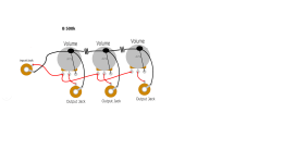
The boxes are easy to assemble - I am using the recipe in the article except for little things like using hide glue I had on hand instead of the stuff recommended.

I figure what this is doing is like good cables - what is revealed could never be revealed by any other method. Some may think it is nothing more than band-aids but I counter what else do we have and we should be grateful for band-aids that work.

I was thinking last night - most of the AC work (I think of Michael Fremer's impressive AC wiring into his listening room) revolves around conductivity - removing obstacles in the path and this is important especially if one uses monstrous amplifiers to drive insensitive speakers which strikes me as wrong but that is another subject - instead of concentrating on radiation. I share with Acosta a suspicion of shielding - of course, if you absolutely need it you have no other choice but to use it - but if you do not absolutely need it it is BAD. So like naturopathic medicine we want to absorb the radiation instead of blocking it - sorry for the awkward analogy but I think it makes sense. Mr. Acosta may very well disagree with all that I have written here. Not to discount a free flow of electrons in any way but the worst aspects of the sound we attribute to our great friend and colleague AC POWER is the radiation that infects everything in its wake.

In my clumsy way I hope I have encouraged the kookiest of you to look into this. As I wrote to my audio friend in Toronto last night, the great Grant Warecki with ears that continue to amaze me, Acosta's concept is valid and important.
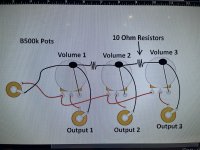
Just try the salt packets in a few "junctions" and hear what happens.
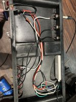
AK4499EQ - Best DAC ever

AK4499EQ - Best DAC

In January 2019 comes the new DAC AK4499EQ from AKM. If you can believe the given values, then this DAC is probably the best that ever existed. Since we can look forward to even better audio analyzers. From the site: It achieves the world’s highest class of low THD+N and high S/N. Samples will be available in January, 2019, and Mass Production starts from May, 2019.


AK4499EQ: THD+N -124dB
AK4497EQ (predecessor): THD+N -116dB


Access Denied
AK4499EQ | Audio D/A Converters | PRODUCTS | Asahi Kasei Microdevices (AKM)

Hornresp

Hi Everyone,

Just letting you know that Hornresp Version 18.00 has now been released.

The Tapped Horn Wizard tool has been significantly enhanced. For a given overall horn length, flare rate and driver specification, the optimum driver position can be determined more easily than before.

Note that there are three ‘Interaction’ options. The operation of the first two should be pretty obvious from the titles. The third ‘L12 & L34 Linked’ setting enables the user to “slide” the driver along the mounting baffle / separating panel towards or away from the 180 degree bend (similar to changing the acoustic path length of a slide trombone).

Hopefully the Tapped Horn Wizard is now a far more useful tool. Enjoy :).

Kind regards,

David

Attachments

  • wizard.jpg
    wizard.jpg
    44.7 KB · Views: 23,649
  • Like
Reactions: 1 user

Hammond 1650E output transformers and colours on the wires

I have bought a pair of used Hammond 1650 E output transformers. I see on the Hammond website that the colors of mine, and the colors of the wires on the secondary side, on the form on the website are different. The colors of mine are black, black with red markings, green, black with green markings. Mine were manufactured in March 2004. Can anyone help me out there?


Tilbakemelding

Google Oversetter​

Attachments

  • 1717135827234.png
    1717135827234.png
    312 bytes · Views: 20

Adding low bass channel to a passive radiator design

Hi all!

I'm new to loudspeaker design. Here is the problem I'm trying to resolve and would love to hear some expert opinions:

I want to add a low bass (< 60Hz) channel to a speaker with a passive radiator (PR) and don't know how to do it to integrate it smoothly.

Some input data:
The PR loudspeaker is 10" Tannoy Red + 10" Scan Speak 25W/8565-00 as PR in 89 liter, damped box. Tannoy uses its native crossover, ScanSpeak completely unconnected.
This is a sample L+R response in my room, amplitude + phase:

Sample Dannoy LF response.jpg


It doesn't look very good but sounds very seducing. I listen near field in a small room, classical repertoire. The bass is really great if not outstanding but a 10" Tannoy cannot obviously produce a lot of it and I like to have more power in the lowest registers and some of that "LF breathing" especially with big orchestral music.

The guy who conceived the speaker tried to add a bass channel to it in a form of a sealed boxed with 15" driver, IIRC low passed 4th order at some 50-60Hz, simultaneously high passing the above design but the point and order is unknown to me. It didn't work, the low bass was "detached" and did not blend in. The suspicion was that the complicated phase behavior of the PR design did not blend in with the sealed box plus the high passing made it even worse.

Does anyone have any experience of designing/adding subwoofers to PR designs? I want to add/reinforce the lowest registers without affecting the great bass I have right now. One idea I have is to add a PR sub with the same ScanSpeak 25W/8565, one active, one as PR, same 89l box. And running the Tannoy PR unfiltered.

Any PR experts/practitioners can comment? Thanks in advance :)

Shunt type volume control for tube preamp

General consensus from what I read is that a straight log pot of good quality is better than any shunt arrangement. So no doubt several replies will confirm this. Downside is that good quality pots, especially stepped attenuators, are expensive.

But supposing, in the interests of economy, you did construct a shunt control for a valve amp or preamp, what is the best you can do? Here we assume a typical DAC input of low output impedance which would be happy into 10K. So I'm assuming that theoretically the shunt resistor should be 10K or more, but please dispute this.

I've made an experimental external box to try out different resistor values. Shunt resistors for first trial are old style black Holco 1W. Pot is 50K log chi-fi Alps. This feeds an amp with a 100K resistor to ground on the input. Results....

38K shunt - law is fine but too much attenuation of the signal
10K shunt - louder and the law is actually quite good.

These are very audibly inferior to a simple 100K Holco input resistor to ground and volume control in software on my Mac Pro with lossless tracks in iTunes.

Please suggest anything that will give better results......

Mark Levinson ML-9 recapping (1985)

Hello to all.

I've decided to recap my old ML-9 amplifier, which, I think, deserve it ;)

At the moment, I'm looking for 1) finding as much and well the same references than the original ones (which is a fancy yet uneasy job ;) 2) finding the right way (procedure) to replace the capacitors on the amplifier board (which seems uneasy too, considering the way it is built, as I'll explain).

I’m not a professional but I’ve got plenty of time, I already recapped several small amplifiers (like some Cyrus 1 and 2 and other electronic devices), and I’m equipped with all the necessary tools. But if it appears that it is impossible for someone like me to achieve the task, I’ll try to find a qualified professional to have the job done…

Then.

1. finding the same references than the original ones. Easy for certain items. Difficult or impossible for some others. Possible with a few references if you buy 10 or 300 of them (depending on the item). For instance, I’ve chosen to replace the original Sprague 36DX 36000uF/100V by new United Chemi E36D101HPN363UEM9N bought from M…r (same voltage/capacity/size) which, I believe, are widely used by Madrigal to recap old ML amplifiers. Those capacitors are not on the signal path and should do the job. Selecting Cornell or Vishay (Sprague) of the same type would have demanded that I take at least 9 of them, which is rather expensive.

I couldn’t find the 10/100V same polycarbonate caps (and as film caps I suspect they are not too bad even after 35 years of use), but I bought East German RFT NOS 10/100 polycarbonate caps, in case (they seem OK, cap 15uF and Vloss 2,5% - acceptable?). I could find NOS Sprague 39D series 520/100V caps, and I’ll check the Vloss and ESR when I got them. Hoping they are OK or that I could reform them if necessary. I could find NOS 10000/10 Frako (same question than previous). I could find new TE1105 250/6V at M…r.

Then I’m wondering what to do with the 672D Sprague 680/6.3V/105° which are used in the DCO suppressor circuit. If I’m not mistaking, they should be on the signal path. Impossible to buy less than 291 units… at 3,5/unit, I won’t do it. So I’m looking to find a substitute, but which? I found this: UPM0J681MPD6TD (UCC). Rippled current is at 825 mA which could match the particular position of these caps. But I’m fairly ignorant about this point (and many others…). A helpful advice will be happily considered ;)

2. Assuming that I found all capacitors needed. The physical operation of replacing them has yet to be done. (!) Rather simple when access to the whole circuit board is open and clear. The power regulation board and the DCO board are in this case. BUT not the amplifier board, which is almost stuck to the large radiator, the transistors being on the outside of the radiator, their pins soldered on the inside of the board, where all the components are. A kind of sandwich, where to take out the board in order to have a full access to the soldering points of the components (the board seems to be a double sided board with different tracks on one side and on the other), you have to unsolder the 10 power transistors and un screw them. Which is a delicate job to do, especially when you see that some transistors pins are VERY close to some components. The pictures show this, I hope.

Then.
What to do? For the first part, advice is required for a suitable match for the two 672D Sprague 680/6.3V/105° in their particular location (DCO circuit).
For the second one, I haven’t taken everything apart yet, hesitating to do that at this point. Do I have to unsolder all transistors so I can have full access to both sides of the circuit board? Would it be necessary, would it be possible (even if not a proper job, I admit) to cut the leads of the existing caps and solder the new ones on them? (please don’t throw too many stones at me ;). Or just unsoldering the defective (read old) parts and solder the new ones on place with enough welding to go through the hole (but not too much)?
I’m trying to understand how this was done by the manufacturer by observing carefully the board and it seems to me that at least the two 520uF Sprague Caps couldn’t be soldered before soldering the transistors… if this had been done, how could they have soldered the last transistor with so little space available? (but this is Mark Levinson and their techs are probably above the average humans about soldering).

Thanks for reading ;) I'll be more than happy to read all of your comments and considerations!

please excuse my poor English and the quality of the pdf docs.

Attachments

  • ml-9 amplifier board and radiator.jpg
    ml-9 amplifier board and radiator.jpg
    615.3 KB · Views: 1,148
  • ml-9 amplifier board reduced.jpg
    ml-9 amplifier board reduced.jpg
    792.1 KB · Views: 1,584
  • ml-9 part DCO board.jpg
    ml-9 part DCO board.jpg
    807.6 KB · Views: 1,032
  • ml-9 regulation board.jpg
    ml-9 regulation board.jpg
    615.2 KB · Views: 1,100
  • ml-9 transistors_radiator.jpg
    ml-9 transistors_radiator.jpg
    808.8 KB · Views: 1,378
  • ML-9_schema-DCO Protector.jpg
    ML-9_schema-DCO Protector.jpg
    698 KB · Views: 1,042
  • ML-9_schema_amplifier board.pdf
    136.9 KB · Views: 423

For Sale Adire Audio Brahma X Mk2 15" 1500w XBL2 subwoofer - Dual 2

Monster subwoofer driver from Adire Audio for sale. Very lightly used. I decided to go with a higher-sensitivity driver instead. I no longer have the box. Local pickup in San Francisco Bay Area preferred.

294-120_ALT_1 copy.jpg

(stock photo)

Details: https://adireaudio.com/product/brahma-x-15/

I paid $824.05 after tax. Asking $400 which is over half off.

Flush-mount ceiling speaker enclosure for Micca M-8C speaker?

First-time post for me. I'm the AV tech at our church, and have cabinet making skills. I recently purchased a Micca M-8C 8" 2-way in-ceiling speaker for our church's front entrance foyer. We have a 100+ year-old building with Lath & plaster ceilings. Using a 16-element stud finder, I thought I located an area free of obstacles. I drilled a 3/8" hole, but when I attempted to cut two lines out from the center of the hole found an electrical conduit on one side and a ceiling joist on the other side.
I want to construct an enclosure for the speaker that will be mounted to the surface of the ceiling. I need some help in understanding the acoustics involved in speaker box construction. The outer dimensions of the speaker are 10.7" diameter, with a mounting depth of 3.5". I am imagining a box that 12" square and 4" high with slots (instead of one or more round port holes) on two or four sides, say 1/4" x some length less than 12" long. Someone indicated I need to obtain the Thiele/Small parameters in order to proceed with a proper design. I've requested this information from Micca. I'm looking for advice on how to proceed. For example, does this box need to be tuned? What do I do with the Thiele/Small parameters if Micca provides them? Thank you! Link to Micca M-8C.

For Sale TDA1541(A)

Hi,

I'm collecting OLD CD players to salvage the DAC's for a next DIY project. I'm have some overstock which I'm willing to sell.
I have 2 TDA1541 + 2x TDA1541A.
All four are pulled from perfect playing Philips CD players. The 'A' versions I have from rather expensive Philips CD582's.

Price exl. shipping is: (prices updated 13/08/2023)
  • TDA1541: €30
  • TDA1541 R1 : €30
  • TDA1541A : €60/pc

Above pieces are very carefully desoldered from the PCB's, no bended pins or damage.
Have no idea what they are worth. The ones I'm finding on the internet are from questionable sources.

Regards

Attachments

  • TDA1541 col 2.jpg
    TDA1541 col 2.jpg
    483.1 KB · Views: 405

ESL Diaphragm coating

I have been reading about coatings until I could stand the subject no more. Sigh.

Seems there is very little consensus out there and quite a few secrets :-(

Mind you, I do appreciate the effort that some people put in in finding a good solution for this problem, and I fully understand if they want to keep their secrets. Besides it is their right to do just that. And there is always the risk that some company would want to run off with the formula and patent it. Talk about scr*** the inventor!

So I have absolutely nothing against secrets!

Having said that, I prefer to use a public domain solution (if at all possible). I like the idea of being able to reproduce my efforts at some other time (or by someone else) without the problems of having a supplier going out of business, or being bound by a promise for confidentiality.

Thus the coating is reduced to the following possibilities that I know of:

1) Graphite rubbing
2) Nylon in methanol
3) Glue
4) Elvamide (possible sourcing problem, better to use option 2?)

How are the experiences with any of the above?
Which one seems best for quality and long term stability?
Are there more solutions (pun intended!) for this?

Iron Pre Essentials Kits For The DIYA Store - Register Your Interest

The Iron Pre is now listed in the diyAudio store for anyone to purchase. No codes or tricks needed.

Until the 'Build Guide / Build Thread' is created, this post will contain all current schematics and notes for the Iron Pre sold through the diyAudio store. Check back frequently to ensure you have the latest files.

Sep 14 2023 - Below is what you're waiting for! See some awesome information and help from 6L6 on the SE build. A new thread and the guide using the web interface will be posted ... soon. Post #2291

1694728999259.png


Background


Hello Happy DIYers / Greedy Boyz!

I am thrilled to announce that Zen Mod's Iron Pre essentials kits will be offered in the DIYAudio store. This is not a group buy. You can learn more about the project in the thread linked below.

https://www.diyaudio.com/community/threads/whats-wrong-with-the-kiss-boy.293169/

Highlights include matched Toshiba JFETs from Nelson Pass and high-nickel CineMag transformers. 6L6 has volunteered to post one of his incredible build guides also.

If you're a Smiths fan, you may ask, How Soon Is Now? They should be available for order before the end of the year. At this time, we have enough parts sourced for 100 SE and 50 balanced kits.

The next obvious question is, how much? Costing is not final yet, but the goal is $100 for the SE kits and $125 for the balanced kits; a tremendous bargain. We have contingencies for all the parts, and we hope that this will be a permanent addition to the store. However, for now, we can only promise what we've got. Get 'em while you can.

Click the link below to see what will be included in the kit, answer a few questions about what you might like to see in the future, and get on the list.

Note - The n-channel JFETs will be 2SK370.

Quick and Dirty Startup Process

This happens after: the boards are stuffed, the AC supply is verified and connected properly, and I/O has been connected. Nothing needs to be shorted.

  1. Set V+ and V-

    Adjust P1 and P2 for each board until
    V+ is +15V0 and V- is -15V0

    GND, V+ and V- pads are clearly marked on PCBs.
    Do not move forward if you cannot adjust the voltages to within 0V1 or if the voltage seems unstable.


  2. Null DC offset
    • SE
      • No jumper caps in place for JP1 or JP2
      • Measure at center pin of JP1 and JP2 NOT between those two pins*
      • Turn P3 / P4 respectively until voltage shows 0V +- 5mV
      • Cap the jumpers for your choice of gain.
    • Balanced
      • No jumper caps on JP+ or JP-
      • Measure at pin 1 of JP+ and JP- NOT between those two pins*
      • Turn P3 / P4 respectively until voltage shows 0V +- 5mV
      • Cap the jumpers.
Do not move forward if you cannot null the offsets to less than +- 5mV
3. Sing Happy Tunes
*Measure at a particular point => Measure between that point and GND.
Updates

4-May 2023

Edited 7-Aug 2023.
All in-line photos have been removed. Please see attached files for all documentation.

5-May 2023

Updated Single-Ended BoM to correct 330R part notations in the gain stage to R28 and R29.

Attached are the Bill of Materials / Parts Lists - Note File Names for Balanced and SE

26 - May 2023

Updated SE and Balanced Bill of Materials to indicate that snubber components should not be installed.

Balanced BoM Filename - BOM_Store_Iron_Pre_Balanced_Dist_v5.pdf
SE BoM Filename - BOM_Store_Iron_Pre_SE_Dist_v5.pdf

27 - May 2023

Updated SE and Balanced Bill of Materials to correct and clearly note which diodes should be installed for input switching.

Balanced BoM Filename - BOM_Store_Iron_Pre_Balanced_Dist_v6.pdf
SE BoM Filename - BOM_Store_Iron_Pre_SE_Dist_v6.pdf

1 - June 2023

Note - No changes required. However, the packing lists some of you will receive may note LM336-5.0. That was a typo; apologies. The correct parts (as supplied and noted in the BoM) are LM336-2.5.

Removed the link to sign up indicating interest in kits. Those currently on the list will get first priority for the next round of kits. After that, they will be sold through the normal process through the store.

6 - June 2023

There are two gorgeous prototype chassis available; one designed specifically for SE, and one for Balanced. You can find some details in post #431. The depth for both chassis is 280mm. There is additional information sprinkled throughout the thread re: acceptable sizes and some potential part numbers for IECs, input / outputs etc. along with pictures of some examples. Please search first before asking chassis questions, and I'd recommend using the latest posts' information. Again, they are prototype chassis, and anything could change at any time until the design is finalized. The best source of information re: the chassis is directly from Modushop until they are sold in the diyAudio store. Timing TBD.

8 - June 2023

Added parts placement and pcb layouts for those interested.

30 - June 2023

V7 - Minor Updates to BoMs. QTY added. Ensure to check quantity per board against the quantity you need for your project. Added links to a popular online website to show examples of parts that will work for the connection between the main boards and the twister boards for input selection / LED power etc. Added generic descriptions for those that would prefer to select their own parts.

1 - July 2023

V8 - Minor Updates to BoMs. Added heatsinks for M3 if 12V relays are used.

7 - Aug 2023

I'm excited to say that more kits will be available very soon for 'round 2'. Continue checking this post (as always) and the thread overall for up to the minute updates.

In his graciousness, ZM has made some minor running changes. Changes are:

  • Updated transformer snubber circuit.
  • Easier positioning / mounting of the CineMag transformers in some situations.
  • Changes to allow easier use of some logic circuits for input switching.

Boards that include the changes will note "2023" vs. "2021" on the silkscreen. The Twister board accompanying the 2023 boards notes V.3. Both 2021 and 2023 boards are included with 'round 2'. You cannot choose which you will receive, and you will not know which you will receive until they arrive. Do not fret if you get a kit with 2021 boards. If you need to use a particular type logic solution, there is a very easy modification previously noted in the thread, and the snubber is not necessary. The changes made were a kindness from ZM, but all 2021 boards can be made to function just like 2023 boards with a few user-tweaks described in the thread.

Note - The attachments have been packaged and note which files to choose for the respective boards. Previous attachments and in-line thumbnails / photos have been removed for clarity. The BoMs have been updated slightly for clarity.

9 - Aug 2023

There is a minor error on the silkscreen for the boards marked Iron Pre SE Zen Mod Labs 2023. The polarity notation for C11 visible when the cap is installed is incorrect. Ignore it.

1691581335126.png


13 - Aug 2023

His Mightiness created two graphics for how to wire standard pots for both SE and Balanced. Attached.

29 - Aug 2023

Minor updates to balanced BoMs. Removed reference to D15.

31 - Aug 2023

Added wiring diagram for AVC for SE. See post #2113 for context.

Attachments

  • Iron Pre 2023 v.3 how to pot.png
    Iron Pre 2023 v.3 how to pot.png
    206.6 KB · Views: 1,279
  • Iron Pre SE 2023 v.3 how to pot.png
    Iron Pre SE 2023 v.3 how to pot.png
    221.7 KB · Views: 1,273
  • 2021.zip
    1.5 MB · Views: 367
  • 2023.zip
    1.4 MB · Views: 597
  • Iron Pre SE 2023 v.3 how to wire AVC.png
    Iron Pre SE 2023 v.3 how to wire AVC.png
    241.3 KB · Views: 1,166
  • Like
  • Thank You
Reactions: 26 users

laboratory audio headphones

Hi everyone .
I would like to buy new headphones, or at a good price on the used market, it depends on the price.
the characteristics must be maximum transparency and no coloring, assuming it exists with these characteristics. practically a laboratory headset to be used to carry out experiments and modifications on the casings.
all this because I want to make an auditory comparison between a neutral sound transmitted by the headphones (which in my opinion are suitable for this purpose. Otherwise I wouldn't know what to use) and the one that comes out of the casing from the speaker (K12 prototype).
the aim is to understand what the defects of the K12 (cabinet) are in order to eliminate or limit them as much as possible to obtain maximum sound quality.
if the headphones also work as a soundproofer to protect my ears I get another important function, so I can use it when I sweep with REW.
I don't know if headphones with these characteristics can also be used to listen to music.
I use a laptop connected to the E-MU 0404 USB sound card.
The card has a headphone output, is it possible to use that directly?
the one below is a link inserted by me and is related to the same topic:
https://www.diyaudio.com/community/...strengths-and-weaknesses.412726/#post-7694471
bye thank you .

custom volume aby pedal

not sure what to call this other then a volume pedal even tho its not a pedal. i have some questions about how to wire it and not sure where to get the information so i figure id ask here.
basically i built this little box that looks like a amp and all it does it have a on/off switch for a power bar i mounted inside, and three volume pots with three outputs. the idea is i play through two amps and this will act like a ABY pedal. the third output is just for extra options (ideally for my rocksmith cable lol),

my problem is wiring it and grounding it, i seem to get a loud buzz from the output and i think its a grounding issue, i know using two amps can cause a ground loop aswell and ive had aby pedals that made this worse so i added some resistors between the grounds, i read on google about that but im not sure even sure about that.

here is the wiring i had

wiring diagram.png image_50438657.JPG image_67530241.JPG

this is what im building is anyone is interested
image_67213057.JPG

Help with Class D Subwoofer Amp stuck in standby / protect

Hey Folks

Have an amp here that's not coming out of standby / or going into protect.

Relay clicks when power button is pressed but led doesn't go green and no output.

Pics of board and schematic attached.

Any pointers on methodical fault finding would be a help

Only thing I noticed on the board - looks like got hot around the 'remote' connector - I've reflowed the four resistors R426 R427 R428 R169 and transistors Q404 and Q405 which also tested as expected with a DMM.

I have component tested the momentary buttons and the the two IRF740 mosfets which are ok.

Looks like the irs2153D is there as a gate driver to protect the fets anyway, and boom I'm suddenly out of my depth on this one. I'm trying to dredge up knowledge I had many years ago but haven't practised in sometime.

Haven't got a scope here, just a DMM and a reflow station.

Any help or pointers greatly appreciated.

Attachments

  • BKA-130-C-r16 Schematic.pdf
    218.8 KB · Views: 7
  • IMG_8235.jpg
    IMG_8235.jpg
    801.7 KB · Views: 13
  • IMG_8236.jpg
    IMG_8236.jpg
    541.2 KB · Views: 10
  • IMG_8216 2.jpg
    IMG_8216 2.jpg
    356.1 KB · Views: 11

6C33CB PP amp with ultra linear

Anybody know if this has been done before? Basically an pentode LTP driving a pair of 6C33's. Trick is to allow negative feedback to the screens of the LPT from the plates of the 6C33. On simulation has a dramatic effect on THD and there seems to be an optimal value for R17. Would this work and am I within the specs for the 6EJ7's. Its a little difficult to get enough output swing to drive the triodes. Any comment would be helpful.

Attachments

  • Screenshot (192).png
    Screenshot (192).png
    56.5 KB · Views: 221

The 15 Song Album collection:

Hi to all,

I just want to make a album for 15 songs time over 16 minutes. It's simple. Each user has to copy and paste adding only one song to the album so in the end it's 12 songs, one per user, and each album has to have a different theme.

Whoever adds the last song of the album gets to say what the the theme for the next album will be and it starts all over again.

Songs over 16 minutes:

1. Pink Floyd - Echoes (23:31)
2.
3.
4.
5.
6.
7.
8.
9.
10.
11.
12.
13.
14.
15.
  • Like
Reactions: 1 user

Third Omicron Headamp Group Buy

After the second Omicron group buy closed in September last year, there has been a number of requests for more boards, so here is another chance to get them. Building Omicron may be a nice summer project! ;) This GB will close at the and of the day on Sunday, June 2, 2024. If you're interested, be sure to sign up before then.

The following four boards (bare, unpopulated, parts not included) are offered in this GB, in any combination:
  • Omicron through-hole PCB: a 80x110mm, two-sided board that carries two amplification channels, optional crossfeed, DC protection circuit, and the output filter. All parts are through-hole and regular sized, so the board is easy to build. The output stage is heatsinked, so the amp can be run at higher quiescent current if needed.
  • Omicron SMT PCB: a 60x90mm, two-sided board that carries two amplification channels, relay-switchable crossfeed, DC protection circuit, and two output filters (one for headphones, one for line output). The board itself serves as a heatsink for the output stages. Most parts are SMT, but with no parts smaller than 1206 or SOT-23, this board is reasonably easy to solder by hand.
  • Omicron power supply PCB: a 130x80mm, two sided PCB that carries an AC mains filter, 230/115VAC mains voltage selector, a power transformer, a pair of regulators, and an quick-turn-off circuit that works together with Omicron's DC protection. This board is optional - you can power Omicron from other suitable power supplies - but it has been tested in multiple builds to work well with the Omicron.
  • Omicron DC protection PCB: a 50x50mm, two sided PCB that carries a copy of Omicron's DC protection. This board is not needed to build the Omicron, which already includes the same DC protection circuit, but may be used with other headamps. The quick-turn-off of this protection works together with Omicron's power supply board.
1716220043416.jpeg 1716220060182.png 1716220070067.jpeg 1716220014990.png
What it is
  • Omicron is a compact, inexpensive and easy to build headphone amplifier with uniquely low distortion, very musical, pure, clean, liquid sound and perfect clarity even in the most harmonically complex pieces. As one of the first GB participants put it, "The clarity is surreal."
  • Designed to work with 32 to 600 ohm headphones and tested with a range of over-the-ear and on-the-ear cans from AKG, Beyerdynamic, Grado, Klipsch, and Sennheiser as well as with lower impedance 16 and 8 ohm headphones, such as AKG's K3003 3-way in-ear monitors; even white Apple EarPods (tethered ones, both 1st and 2nd generation) sound great with Omicron, too!
Features and benefits
  • Ultra low distortion; at -140dBc, Omicron is an order or two more linear than other "high-performance" and "ultra-high performance" headamps. Omicron adds neither dirt nor fairy dust, offering exceptional clarity and fluidity of sound. With Omicron and a good pair of cans, music just carries you away. And if you want to look at the measurements, we have them, too.
  • Simple and inexpensive to build. One channel of Omicron is built with just one dual opamp, two transistors, ans a bunch of resistors and capacitors. The circuit allows broad opamp substitution and has been tested to work well with many modern (e.g. OPA1642) and not-so-modern (NE5532) opamps. At the time of the first GB, the total cost of parts to build one Omicron board (two channels) was just $42.
  • Built-in fast (10ms) and sensitive (80mV DC) headphone protection.
  • Built-in optional cross-feed circuit, helping to create a more realistic soundstage.
  • Compact and easy to build.
Pricing
  • $5 per one protection board, $15 per any other one board, plus shipping.
  • Shipping is calculated at checkout. U.S. Postal Service offers inexpensive shipping to the continental U.S. starting at $3.80 (USPS Ground Advantage) with tracking or $1.60 (USPS First Class Mail) without. International shipping (USPS First Class International Package) will cost somewhere between $16 and $20, depending on the destination. Should you want to buy something else from me, I of course can combine shipping.
Technical details
  • The main thread has lots of details, including full schematics, part lists, board outlines, assembly instructions, and more. The first post in the main thread includes a list if links to most useful posts. I will review the thread in the coming days and update it as needed.
  • The DC protection has its own thread.
  • Part lists aka BOMs has been published for each board. I will update the BOMs over the next couple of weeks making sure all parts are available and any errors and omissions discovered so far are corrected.
  • We support Omicron builders in the main thread.
If interested in purchasing any of these boards, please reply to this thread. Copy this sentence along with everything below into your post and add your own line as follows:

(1) Your name here on diyAudio -- (2) TH board, pieces -- (3) SMT bare board, pieces -- (4) PSU board, pieces -- (5) DC protection boards, pieces, -- (6) Country to ship the board(s).

Try to preserve formatting.

Running List for Subscription:

drof -- 1 -- 1 -- 1 -- 0 -- Poland
Brakspear75 -- 1 -- 0 -- 1 -- 0 -- UK


This group buy will close on Sunday, June 2, 2024. Be sure to sign up before then.

Rebuilding and replacing old bridge rectifiers in vintage gear

This questions specifically involves the S5151 and S5151R which are dual diode devices with either common cathode or common anode and the pair are used in many vintage pieces of equipment to rectifier the AC coming from the secondary windings of the power transformer. In all the years I have been doing this I have read, been told that they are 5A diodes. In a pretty much identical case is the SS3 and SS5, the SS3 being rated for 3.5A and a smaller version of the package and the SS5 being rated 5A and the same size as the S5151. Unfortunately there are no data for the S5151. There are some threads I came across where members were asking about changing these out with discrete components and members like Echowars and Avionic which definitely know their stuff recommended 5 amp diodes as replacements like the HER504.

So I showed my replacment of these dual diode packages using MUR550 as I wanted ultrafast soft recovery diodes in place. They are 5A 570v rated. There is one full bridge for each channel of amplification on a Pioneer SX-1250
IMG_1259.jpeg


It was then brought up by another member, I won’t call him out (hopefully he’ll respond here, but he too knows his stuff as well), that the S5151 may not be 5A rated. He brought up the fact that the SX-1050 uses a 20A rated rectifier, so 10A per channel for less output power. So why a smaller rectifier for more power? I suggested that the rectifier may have been overkill, they could have put a 30A or 40A in there.

I then brought up the fact that the SX-950 which is 85 watts per channel, so 170 total (10 more watts total than each channel of the SX-1250) used a quad of the SR3AM diodes, both channel share the one bridge rectifier. The SR3AM is rated for 2A continuous or 3A with a heatsink which they didn’t use.

He then brings up a conversation that he was having with someone wanting to use 1N5404 (3A rated) in the SX-950, but he felt they weren’t adequate and recommended the need for 6A rated diodes. Why would an amp that came from the factory and has been working for nearly 50 years on 2A rated diodes (3A with heatsink) need 6A? The SX-950 runs at lower rail voltages than the SX-1050 and SX-1250.

So I figure if the SX-950 can make 170 watts output using 2A (3A with heatsink) diodes why can’t the SX-1250 make 160 watts using 5A diodes? I’m still convinced that these S5151 devices are 5A. I set up the bride rectifier so that I could measure the current in the SX-1250 and into clipping the amp heavily the highest I saw was a little over 900mA, but of course I wasn’t seeing peaks.

Regardless I put the SX-1250 back together with these new 5A MUR550s installed and it’s been playing for over 24 hours straight, blasting it pretty loudly during the daytime hours playing into my ADS L1590/2 and ESS AMT 1B. They may not be the most demanding load, but it’s been perfectly fine.

But for me it’s down to the fact the SX-950 makes slightly more power total on a lower current rated bridge rectifier and that for as long as I can remember the original has always been thought to have been a 5A device.

Thoughts?

Dan

Luxman L-100

Hi experts,
I am repairing Luxman L-100. There are two driver circuits L649 for each channel driving the power transistors. A power supply that is 55 volts DC feeding to these circuits. When I pull up the connector of one channel supply, Left Channel or Right channel it works only that channel which has power supply but once I put connector of both channels, front light keep on flashing. Only one channel at a time. If anybody guide me, I will be thankful to you. Waiting for comments from experts.

Yes, I swap both Channel's power stage but behaviour of amp remains same. This is clearance indication that something wrong with the power supply. It has not enough power to drive two channels together.

Wordle

When I was young, we spent hours on end playing what we called word game. Same rules but it was always 4 letter words.
I was introduced recently to this new sensation and tried it today. Now I know it's beginners luck, but first time out I got it in 3 words.
I think I'll try again and let it bring me back to earth.
Who else is doing this?

Attachments

  • DSCN8507.jpg
    DSCN8507.jpg
    65.5 KB · Views: 1,004

Muses Volume

v1 Documentation

Microsoft OneDrive - Access files anywhere. Create docs with free Office Online.


Update 2021 for Muses v2 ( Muses 72323 )

One Set include:

- programmed Microcontroller
- unsoldered Controller PCB
- 1 or 2 (or more) unsoldered Muses PCB

The price for each v2 PCB is 12€, for the programmed Controller 16€.
Worldwide shipping by registered mail depending on destination.


v2 Documentation
Microsoft OneDrive - Access files anywhere. Create docs with free Office Online.

Mouser BOM
Muses Volume

Pioneer SX-950 issues

I'm restoring a Pioneer SX-950 and I noticed that the protection relay has no snubber diode across the relay coil. I have never seen this and I have to wonder if anyone has encountered a blown protection relay driver transistor in an SX-950.

It's possible that Pioneer was concerned about the snubber diode slowing down the relay too much and indeed they do, but a 24 Volt Zener back to back with the snubber does wonders for that. The relay coil is 24V.

I do run into some strange design decisions made by Pioneer and others, and sometimes I think that they were gambling with the design based on cost but some of the issues seem to be oversights and even a lack of knowledge at the time that we now take for granted. It's difficult to be cetain about these things.

The SX-950 also has a DC nulling system that I have seen fail and cause the protection relay to trip. The SX-880/890 seems to be the worst for this but the nulling circuit in that case needs to be recalibrated as the temperature sensing transistor they used ages.

This is my first deep dive into an SX-950 and I'm sure that there are other quirks. It should be interesting. In general it's a pretty magnificent piece of equipment and I look forward to giving it a listen when it's finished.

What’s On the Bench Tonight (OBT)

I thought it would be interesting to have a thread where I could talk about what’s OBT (on the bench tonight) - or what do I have to work on. A good chance to show what sort of projects and stuff I am working on.

I also invite folks to post their stuff here if they want - especially if it involves stuff from my shop!

I know there are folks working on FH9HVX, Alpha Nirvana, SLBs, SFPs, Aksa Lender’s, Yarra’s, and Rockville speakers, 10F/RS225 TL speakers, foam core builds, etc. please share what you are working on Tonight!

To kick it off, here is what I will be doing: some SMT reflow soldering of the LU1014D power JFET (I think it is a SIT) TO-247 IMS adapter boards. These will be a test batch to check to make sure they work. There is a GB here - I won’t be running it and the boards can be ordered by anyone as the Gerbers are posted free for all to use.

952212d1621191397-lovoltech-lu1014-power-jfet-buy-d12682ba-6848-427e-a3d4-ef3bdfbf30c7-jpeg


952213d1621191397-lovoltech-lu1014-power-jfet-buy-7130aeea-35a4-44ba-9104-a2039d8dc655-jpeg


Woofertester has sent me a batch of matched LU1014D’s to install on these boards. These aluminum substrate boards will allow these peculiar power JFETs to be mounted in an underhung fashion like a conventional TO-247 MOSFET. They should be much easier to use. Also, Nelson Pass is giving away a bag of these unobtanium SITs to they DIYA community. Woofertester is doing the matching and WG45 is handling the GB. Thanks to JPS64 for the awesome layout of this metal substrate adapter board. Thanks to Nelson Pass and Woofertester for the LU1014D’s, and thanks to WG45 for handling the GB that is off to a roaring great start. I can’t believe we have 101 pairs of these adapter boards on the interest list already!

So that’s What’s OBT for me.

What’s OBT for you guys? :)

SET amp power transformer hotter with KEF speakers

Hello, I have got a Line Magnetic Mini 218ia, single ended triode, 3+3 watt. The room is not small by italian standards, 46 square meters, but t is a nearfield listening set up, I'm about 2.5 meters away from the speakers.

I have been driving with it a couple of Triangle Plaisir Lymna bookshelf speakers, rated at 90 db/1w/1m, nominal impedance 6 ohm, minimum impedance 4.1 ohm. These are Triangle data. The 90 db of sensitivity may be a bit overrated but it worked well. I used the 4 ohm tap and listened with the volume knob at 9 or 10 o clock.

Line Magnetic specify that the amp can drive 6 ohm speakers, they say to try both the 8 ohm and 4 ohm taps to get a better result.

I now got a couple of Kef Coda 7 from the late nineties. Rated by Kef at 91 db sensitivity. Nominal impedance 6 ohm. I found an old online review where they measured a minimum impedance of 4.6 ohm and a slightly lower sensitivity, 90 db 1w/1m. They didn't talk about phase angle.

These Kef are more efficient than the Triangle, I use the 4 ohm tap and listen with the volume knob at only 7 o clock.

I prefer these, they have got higher sensitivity and a more british, relaxed sound. But the amplifier power transformer gets hotter with these. It is not scorching hot to the point of getting burned, just hotter. On paper these shouldn't be a very difficult load for a tube amp, should they? I can't hear problems with the bass or signs of distortion. I have tried 4 and 8 ohm taps but they seem to work better with the 4 ohm.

Is the power transformer higher temperature worrying? Should I stop using the Kef?

Thanks in advance
Projects by fanatics, for fanatics
Get answers and advice for everyone wanting to learn the art of audio.
Join the Community
501,779
Members
7,577,071
Messages

Filter

Forum Statistics

Threads
392,381
Messages
7,577,071
Members
501,779
Latest member
tryfon_2l